


XL-2000
14
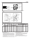
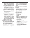
BURNER DATA - RIELLO (continued)
REGULATION OF THE TURBULATOR AND AIR SHUTTER
F
OR PROPER COMBUSTION
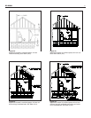
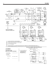
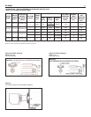
Turbulator Setting
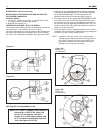
1. Loosen nut, 1, then turn the screw, 2, until the index marker,
3, is aligned with the correct index number.
2. Retighten the retaining nut, 1.
TURBULATOR SETTINGS - RIELLO 40 SERIES
The numbers on the casting are there to denote the high and low
end of the scale - in all cases the first mark is “Zero”.
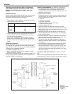
T
he air/oil ratio depends on accurate setting of the turbulator disc.
Be careful when making this adjustment as an incorrect setting
will result in an unsatisfactory installation. See figure 9A and 9B.
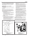
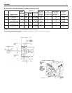
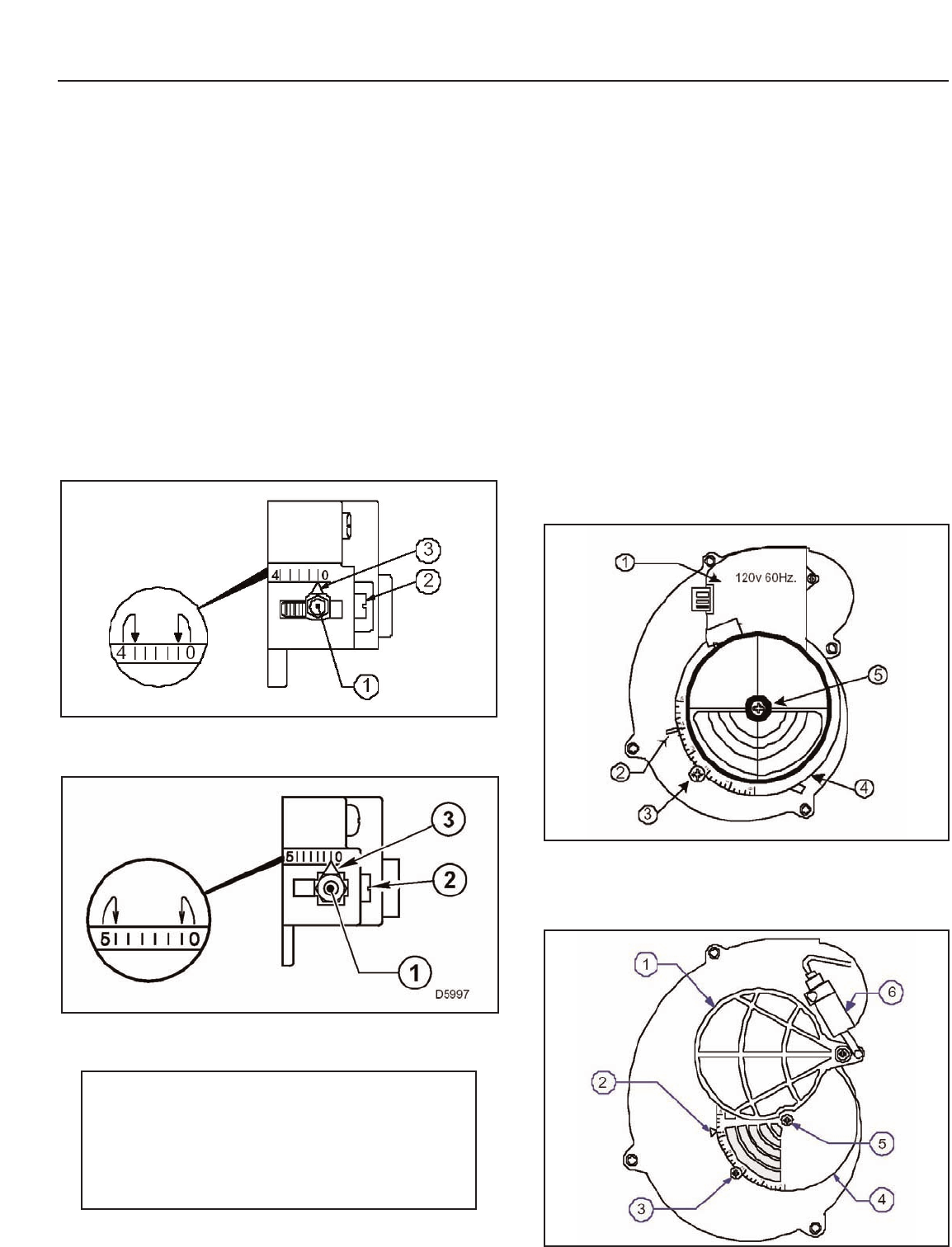
1. Regulation of the combustion air flow is made by adjustment
of the manual AIR ADJUSTMENT PLATE (4) after loosening
the FIXING SCREWS (3&5). The initial setting of the air
adjustment plate should be made according to page 13.
2. The proper number on the manual AIR ADJUSTMENT PLATE
(
4) should line up with the SETTING INDICATOR (2) on the
fan housing cover. Once set, the air adjustment plate should
be secured in place by tightening SCREWS 3 and 5. For F-10
model, manually open and release the hydraulic air shutter to
ensure it has free movement.
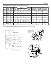
3. The final position of the air adjustment plate will vary on each
installation. Use instruments to establish the proper settings for
maximum CO
2
and a smoke reading of zero.
NOTE: Variations in flue gas, smoke, CO
2
and temperature
readings may be experienced when the burner cover is
put in place.Therefore, the burner cover MUST be in
place when making the final combustion instrument
readings, to ensure proper test results.
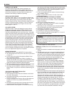
Figure 9A
Figure 9B
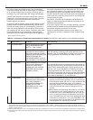
Note: For F-3 and F-5 models, the air shutter is
operated on a 120V 60 Hz.
motor, the
burner will not operate until the air
shutter is in its fully open position; and
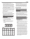
for F-10 model is operated by Hydraulic
Jack. (see figures 10 A & B).
Figure 10A
Model F-3, F-5
Air Adjustment
Figure 10B
Model F-10
Air Adjustment
SETTING THE AIR ADJUSTMENT PLATE