


DOMESTIC HOT WATER
For Indirect-fired storage water heater application, see
S
lant/Fin publication WH-10, Sizing Guide WH-SG and
Installation manual WH-40.The installation manual includes
several control systems and relay centers for space and
domestic water heating in addition to plumbing.
INSTALLING THE BURNER
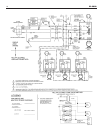
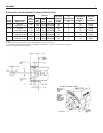
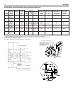
See Burner Data, pages 11 and 12, and Burner Manual sup-
plied with burner. If burner is not mounted as received, mount
t
o boiler, placing flange over mounting studs. Use gasket
between flange and boiler. Distance between flange and nose
of burner must be as shown on pages 11 and 12. Check to
see that nozzle and settings are as given in burner data
tables, pages 11 and 12.
OIL SUPPLY PIPING
Install the oil tank or tanks and piping from tank to burner.
Follow local codes and practices, INSTALLATION OF OIL
BURNING EQUIPMENT, NFPA 31, latest edition, and the
instruction sheet attached to the oil burner pump. A one-pipe
system should be used for gravity-fed fuel systems and for lift
systems, where the total lift is less than 8 feet. Where the total
lift is greater than 8 feet, a two-pipe system must be used. In
some instances, local codes may require a two-pipe system
for below grade fuel oil tanks. Be sure to set up the fuel oil
pump for the piping system used; follow the instructions
attached to the pump. Be sure to include a good quality, low
pressure drop fuel oil filter in the supply line from the tank.
This is necessary, especially at low fuel oil flow rates (small
nozzle sizes), to prevent nozzle plugging. Fuel oil shutoff
valves should be installed at the burner on the supply (and
return if two-pipe) to facilitate servicing. See Slant/Fin publica-
tion on one-pipe and two-pipe fuel oil systems.
WIRING THE BOILER
(see National Electric Code ANSI/NFPA 70-latest edition)
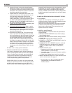
A. The wiring diagrams for the burner and boiler may be found
on page 10.
B. 24 volt control wiring should be approved Safety Circuit
wire, protected as needed.
C. Power supply wiring to the burner must be 14 gauge, as
required, and should have a properly fused disconnect switch.
120 volt wiring to pumps and safety controls must also be 14
gauge.Wire must be enclosed in approved conduit.
D. The wires supplying power to the burner MUST go through
the quick disconnect plugs provided with the boiler.
E. All wiring must be installed in compliance with the National
Electric Code, or any local or insurance codes having juris-
diction.
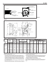
VENT PIPING AND DRAFT REGULATOR
(see NFPA 31, latest edition)
A. Vent connectors must be the same diameter as the boiler
flue collar. (See page 2)
B. Vent pipes and breeching must be pitched upward a mini-
mum of 1/4" per foot.
C. Connect vent pipe to the chimney using as few elbows as
possible and as short as possible within NFPA 31 or
authority.
D. Horizontal vent connector into the chimney should not be
inserted beyond the inside wall of the chimney.
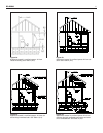
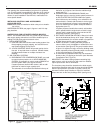
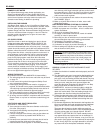
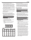
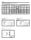
E. Install barometric draft regulator on horizontal breeching,
near chimney, with hinge horizontal and face vertical condi-
tions permitting as in Figure 3a. See Figure 3b as a second
choice. See manufacturer's instructions packed in carton
w
ith barometric draft regulator.
F. If two or more appliances are used on the same chimney,
see CHIMNEY, page 3.
G
. Make up all joints with minimum air leaks, secure with
sheet metal screws.
P
RECAUTIONS BEFORE STARTING OIL BURNER
Make a positive check of A through F before starting burner:
A. Boiler and system are full of water. All air is vented from
system. See below.
B
. All wiring is completed. See page 10.
C. Oil supply is connected to the burner; nozzle is installed
correctly; oil valve is open at tank.
D. Main cast iron door on which burner is mounted is bolted
shut and fiberglass rope seal is making good contact.
E. Smokepipe is connected to chimney.
F. All combustible materials are cleared away.
G. Combustion air supply is provided. See page 3.
H. Burner settings are adjusted as per pages 7, 8, 11 and 12
and as shown on boiler jacket.
W
ARNING: NEVER OPERATE any natural draft* boiler
(XL-2000 boiler is a natural draft boiler) with zero draft or
overfire pressure: early failure of the burner, nozzle and
chamber is inevitable if you do. Use a draft gauge, and
make sure that overfire draft* is .02" to .04", during all
operating conditions.
* Draft is negative or suction pressure.
START-UP (COMBUSTION TEST INSTRUMENTS MUST
BE USED)
A. Make sure the boiler is installed and wired properly and is full
of water.
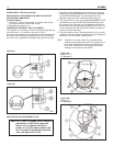
B. The observation port cover is mounted on the hinged burner
mounting door (see figure 2 on page 2). NEVER touch the
port cover or any surrounding surfaces with hands.They may
be HOT. Use tools. Loosen the screw that fastens the obser-
vation port cover, swing the cover open and tighten the
screw. See the burner instructions for bleeding air, etc. Step
away from the boiler and start the oil burner.
C. IMMEDIATELY, set burner air bands to obtain a bright fire
without smoke or oil stain. Set the DRAFT REGULATOR to
obtain .02" overfire draft*.Take draft reading through slot in
observation door after first closing the observation door.
D. Tighten the observation door screw. Allow the burner to fire
for at least one hour total firing time, to bake out the volatile
binders in the combustion chamber before taking final com-
bustion readings.
E. By alternate adjustment of the barometric draft regulator, the
burner air regulation and head regulation devices (whichever
apply), set for a zero to a trace of smoke and 12% CO
2
.
Then open the air bands or shutter (whichever apply) an
additional 1/8".This should result in zero smoke with NO raw
oil on the smoke paper and a smooth light-off. DO NOT
ATTEMPT TO SET FIRE BY EYE. Flame retention burners
may appear efficient and smoke free from an inefficient 7%
up to an overly high 14% CO
2
. However, a very low CO
2
can
also result in poor ignition and raw (unburned) oil entering the
fire box. At very high CO
2
, any slight decrease in air flow for
any reason will cause incomplete combustion, with high
XL-2000
7