


XL-2000
6
The opening size recommendation just given is for guidance
only. It is the installer’s responsibility to provide air for combus-
t
ion and ventilation to all appliances, under all operating con-
ditions, for each installation. See NFPA 31, latest edition for
more specific details.
I
NSTALLING CONTROLS AND ACCESSORIES
ON BOILER UNITS
Notes
:Jacket must be installed on boiler units prior to installa-
tion of trim.
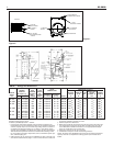
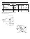
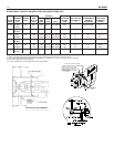
WATER BOILER TRIM, see page 2, figures 1 and 2 for tap-
ping locations.
WATER PIPING FOR HOT WATER HEATING BOILERS
NOTE: On knocked-down boiler only, jacket may be installed
after supply piping connection, but must be installed prior to
adding trim and piping returns and drain valve.
I. CIRCULATING SYSTEM
A. FORCED CIRCULATION hot water heating system: Use
the top tapping as supply tapping, and use the front or
rear bottom tappings for the return.
B. A FLOW CONTROL VALVE will prevent gravity circula-
tion and is required when an external tankless heater,
an indirect water heater or multiple circulators are
installed.
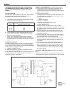
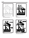
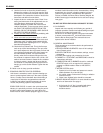
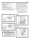
II. AIR CONTROL SYSTEMS
A. DIAPHRAGM-TYPE COMPRESSION TANKS are used
to control system pressure in an AIR ELIMINATING
SYSTEM: an automatic air vent is used to REMOVE air
from the system water. (See figures 5 and 6)
If system pressure needs further control, add an addi-
tional tank or install a larger capacity tank.
The automatic air vent should be installed in the top of
the boiler, as in figures 5 and 6 and at radiation high
points (see “C”).
B
. CONVENTIONAL COMPRESSION TANKS (non-
diaphragm type) are used to control system pressure in
an AIR COLLECTING SYSTEM. Within the system,
a
fter initial start-up and venting, air is collected in the
tank and acts in contact with the water to control pres-
sure (see dashed area in figure 5 and paragraph “E”).
A
ir is not vented from this system except at radiation
high points (see “C”).
If system pressure needs further control, add another
tank in parallel with the original tank or install a large
capacity tank. Locate the tank at the inlet end of the
p
ump near the boiler. (See figure 5)
C. HOT WATER RADIATION VENTING - Manual air vents
should be installed at the top of all "drops" (where pip-
ing goes downward). Air must be vented or purged from
all zone lines to permit proper system heating.
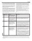
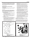
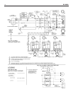
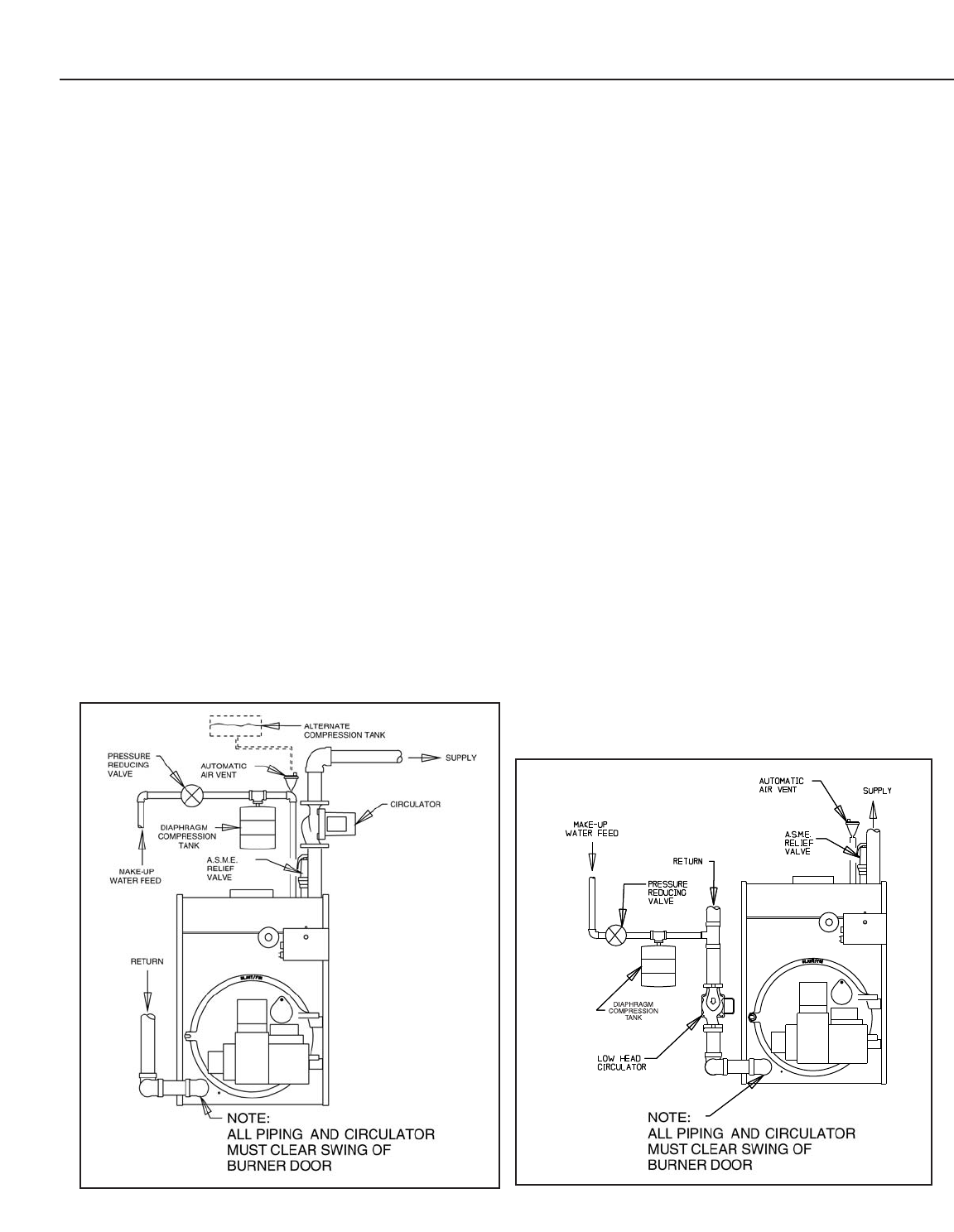
D. PUMP LOCATION - Locating low-head pump(s) on
return to boiler is only acceptable in residences of one
or two stories. (See figure 6) The pump location shown
in figure 5 is required in large, multi-story building instal-
lations, especially when high-head pumps are used and
is also recommended for all applications.
E. A conventional compression tank may be connected
directly to the 1/2" tapping on the boiler (see “Alternate
Compression Tank”, figure 5).
IMPORTANT: Hot water heating systems containing high
water volume, such as would occur with cast iron radiation,
require special care with air elimination.
The circulator pump should be located on the boiler supply
pipe and the expansion tank and air scoop should be located
near the pump suction. (as shown in figures 5 and 6) For
alternate circulator pump location on return for low-head
pumps and one or two story buildings ONLY (see figure 6).
Figure 5. Air Eliminating System or Alternating Collecting
System
Figure 6. Alternate Air Eliminating System