VICTORY 1
9
B
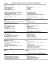
URNERS FAIL TO OPERATE
C
AUSE
1. Safety pilot out, or flame too low.
2. Gas supply valve shut off.
3. Electric switch open.
4. Blown or defective line fuse.
5. Operating or limit control contacts open or dirty.
6. Defective gas valve or pressure regulator; or plugged bleed
l
ine.
7
. Defective low voltage transformer of aquastat relay.
8
. Obstruction at main burner orifice.
9. Break in wiring or loose contact at control terminals.
10. Improper wiring.
11. Improper controls.
12. Defective air flow pressure switch.
13. Rollout switch open.
BURNERS WILL NOT SHUT OFF
CAUSE
1. Defective operating control, gas valve, or high limit control.
2. Improper wiring or short circuit.
FLASH BACK - BURNING AT ORIFICES
CAUSE
1. Manifold gas pressure too low.
2. Improper primary air adjustment.
3. Gas regulator bleed too slow.
4. Burrs on orifice.
5. Improperly drilled orifice plugs.
6. Leaking automatic gas valve.
7. Adverse draft condition in boiler room.
8. Low main gas pressure.
9. Safety pilot improperly installed.
DELAYED IGNITION
CAUSE
1. Pilot flame too low.
2. Pilot burner ports or pilot orifice clogged.
3. Burners or orifices out of alignment.
4. Excessive primary air.
5. Excessive burner input.
6. Adverse draft condition in boiler room.
FUMES AND GAS ODORS
CAUSE
1. Leaks in gas piping or accessories.
2. Gas leaks in service line or meter connections.
3. Blocked chimney.
4.
Boiler fluew
a
ys blocked with soot.
5.
Undersized breeching or too many turns in breeching.
6. Adverse draft condition in boiler room.
7. Ov
erfir
ing.
CONDENSA
TION IN BOILER FLUES OR IN
VENT SYSTEM
CAUSE
1. Underfiring.
2. Boiler water maintained at too low a temperature level.
BURNER SHORT CYCLES
CAUSE
1. Thermostat heat anticipator set too high.
2. Excessive pressure drop in venting system.
3. Blockage or restriction in venting system.
4. Faulty air flow proving mechanism.
R
EMEDY
1. Check, clean, re-light. See instructions.
2. Open gas valve(s).
3. Close switch.
4. Replace fuse.
5. Check control. Clean contacts or replace control.
6. Repair or replace.
7
. Replace aquastat.
8
. Check, clean and reinstall.
9
. Check with test-light and correct.
10. Check and correct in accordance with wiring diagrams
included with appliance instructions.
11. Install proper controls.
12. Check and replace if necessary.
13. Replace rollout switch (inspect flue passages prior to
replacement).
REMEDY
1. Check, repair or replace.
2. Check wiring and controls.
REMEDY
1. Adjust to proper manifold pressure.
2. Adjust air to produce soft, clean flame.
3. Adjust bleed opening.
4. Remove burrs.
5. Install orifice plugs with proper drilling.
6. Repair or replace.
7. Check air supply and venting system.
8. Contact utility.
9. Correct to manufacturer's recommendations.
REMEDY
1. Increase gas supply to pilot.
2. Clean ports or orifices.
3. Realign burners or manifold.
4. Adjust primary air shutters.
5. Check and reduce to input shown on rating plate.
6. Check air supply and venting system.
REMEDY
1. Locate leaks and repair.
2. Close service supply valve - shut down appliance and
notify utility.
3.
Check and repair chimne
y
.
4.
Clean flueways and adjust burners as described in the
installation instructions.
5. Chec
k man
ufacturer's recommendations
.
6. Check air supply and venting system.
7. Adjust gas input to that shown on boiler rating plate.
REMEDY
1. Increase firing rate to that shown on rating plate.
2. Set low limit controls to maintain a higher water tempera-
ture. If boiler is not equipped with low limit replace with
one which has a combination low limit/high limit aquastat.
REMEDY
1. Reset anticipator to *amps.
2. Reroute and/or shorten venting system.
3.
Chec
k for blockage or restriction.
4. Consult factory.
GENERAL TROUBLESHOOTING GUIDE FOR SERVICEPEOPLE
*L8124=.20 amps, L8148=.20 amps, R845A=.40 amps


