555970 MARK V – MOUNTED OVERARM PIN ROUTER
16
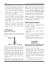
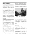
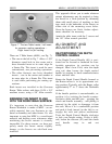
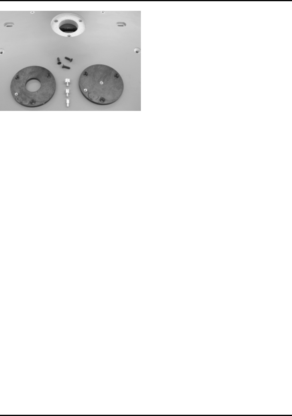
There are 2 Table Inserts (60/61), see Fig. 7).
• The one on the left in Fig. 7 offers a 1-3/8"
diameter round hole in the center and a
brass threaded insert at its outer edge for
a Starter Pin. This insert is used for most
conventional, non pin-routing operations.
• The other features two brass threaded
inserts...one in the center and another at
its outer edge for a Starter Pin. This insert
is used when performing pin routing op-
erations.
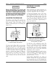
Both inserts are installed in the Overarm
Router Table surface with three 10-24 x 3/4"
machine screws, using a 1/8" Allen wrench.
BRINGING THE INSERT FLUSH
WITH THE WORKTABLE SURFACE
It’s important to note that the Overarm
Router Worktable is made of MDF... an un-
stable material that can fluctuate in size
based on humidity and other factors. It’s also
important to note that MDF is a wood-based
material and holding exact tolerances when
machining the Insert cutouts is virtually
impossible. For those reasons, we have pur-
posely made the Insert cutout slightly
deeper, so the Inserts are sub-flush once
installed.
This approach allows you to make whatever
minute adjustments may be required to bring
the Inserts to a flush position by shimming
them with small pieces of masking or duct
tape stuck to the underside of the Inserts on
either side of the mounting screw holes.
Once the Inserts are flush, further adjust-
ments shouldn’t be necessary.
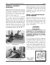
Attach the table insert with the 3 screws and
the 1/8" Allen wrench provided.
ALIGNMENT AND
ADJUSTMENT
RE-POSITIONING THE DEPTH
CONTROL HANDLE
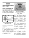
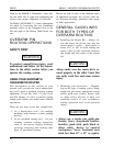
If the Depth Control Handle (40) is posi-
tioned too far forward or backward for com-
fortable operation, its position can be
changed. Here’s how. First, raise the depth
stop rod, then loosen the depth control
handle by twisting its knob counterclockwise
about one-half turn.
Rotate the Depth Control Handle forward so
the Router motor is in its approximate cut-
ting position (Typically with the Router collet
approximately 2" to 3" above the Worktable
surface.)
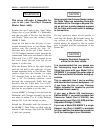
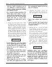
If the handle position is uncomfortable, re-
position it by twisting the handle counter-
clockwise about one-half turn...grasping the
clutch and handle assembly. .. and pulling it
outward (to the right) to disengage it from
the rack. Move it to a comfortable position
and push it back inward (to the left) to re-
engage the rack and pinion mechanism.
Twist the Depth Control Handle clockwise
to lock your height setting. If this is diffi-
cult, loosen the setscrew (41) until the clutch
and handle snap in and out
easily.
Figure 7. The two Table Inserts: Left insert
for common routing operations –
Right insert for pin routing.


