555970 MARK V – MOUNTED OVERARM PIN ROUTER
14
CAUTION
Over-tightening the Motor Bracket nuts
may cause damage to the motor and/or
housing of your router.
INSTALL THE REAR GUARD AND
DUST COLLECTOR ASSEMBLY
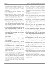
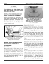
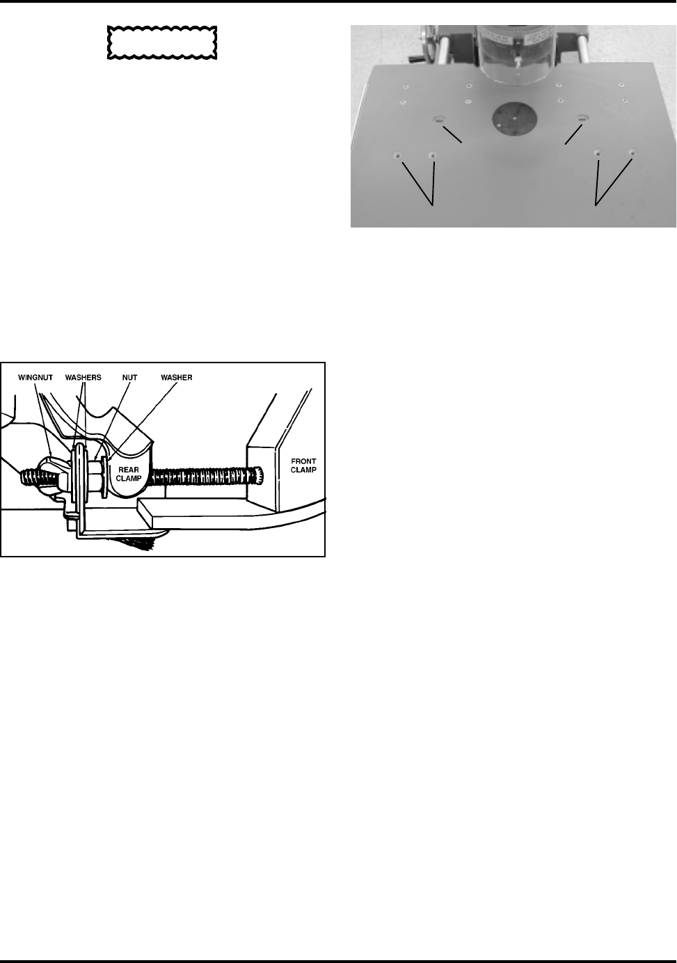
Install a flat washer over each stud of the
front Motor Clamp, and then slip the rear
guard/dust chute with strip brushes onto
the clamp studs and secure with two more
flat washers and wing nuts. See Figure 5 for
correct assembly order.
MOUNT THE OVERARM ROUTER
TABLE ONTO THE MARK V
WORKTABLE
Model 500
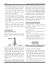
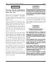
Remove the MARK V Table Insert. Use the
two buttonhead Allen capscrews with wash-
ers to mount the Overarm Router Table to
the MARK V Worktable by inserting them
through the two elongated mounting holes
in the Router Table and threading them di-
rectly into the Model 500 MARK V Table In-
sert mounting holes (See Fig. 6).
Models 505, 510, 520
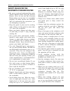
Use the sliding T-nuts and 1/4"-20 flat head
machine screws provided. Lay the Router
Table right-side-up on a flat surface in front
of you with the eight threaded insert holes
away from you. You will notice two pairs of
countersunk holes in the Table surface, about
7-1/2" in from the “front” edge of the Table
(See Fig. 6). These are the holes you will use
to mount your Overarm Router’s Table to
your Model 505, 510 or 520 MARK V’s Work-
table.
For the majority of your conventional and
pin routing operations, you will use the two
left holes in each pair to mount the Table to
the “front” Miter Gauge slot in your MARK
V’s Worktable. This approach will provide
the maximum workpiece support in “front”
of your Router bit and motor.. . and allow
you to use your Two-Piece Router Fence (in-
cluded).
If you would prefer to have more workpiece
support “behind” your Router bit and mo-
tor, use the two right holes in each pair to
mount the Table to the “back” Miter Gauge
slot in your MARK V’s Worktable. When us-
ing this approach, the Table must be rotated
180° and installed with the eight threaded
Fence inserts toward the “front” of the Table.
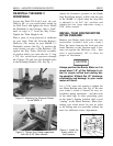
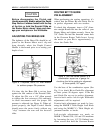
Figure 6. Use the left hole of each pair
when mounting the Worktable on
Model 505, 510 and 520 MARK V’s for
most applications. Use counterbored
slots for Model 500.
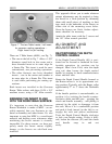
Figure 5. Overhead view of proper motor
clamp hardware assembly order
(looking down from above).
FOR MODELS 505, 510,520
FOR MODEL 500


