


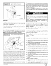
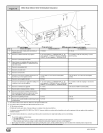

7. Tighten the three (3) or four (4) screws that secure the venter
assembly to the collector box. Do tighten screws enough to
compress venter gasket.
8. Replace power leads to venter motor and reconnect hose to
pressure switch.
NOTE: Unused open vent hole must be covered. A Vent Cover is
supplied with Vent Pipe Shield Kit NAHAOO2VC. A 55/16" diameter
Vent Cover is available separately from your distributor, or one can
be fabricated with sheet metal for all side vent installations.
4. Combustion & Ventilation Air
CARBON MONOXIDE POISONING HAZARD.
Failure to provide adequate combustion and
ventilation air could result in death or personal
injury.
Use methods described here to provide
combustion and ventilation air.
• Cleaning solvents (such as perchloroethylene).
• Printing inks, paint removers, varnishes, etc.
• Hydrochloric acid.
• Sulfuric Acid.
• Solvent cements and glues.
• Antistatic fabric softeners for clothes dryers.
• Masonry acid washing materials.
Outdoor Combustion Air Method
Furnaces require ventilation openings to provide sufficient air for
proper combustion and ventilation of flue gases. All duct or open-
ings for supplying combustion and ventilation air must comply with
the gas codes, or in the absence of local codes, the applicable na-
tional codes.
Combustion and ventilation air must be supplied in accordance
with one of the following:
1. Section 8.3, Air for Combustion and Ventilation, of the National
Fuel Gas Code, (NFGC), ANSI Z223.1-2002/NFPA 54-2002
in the U.S.,
2. Sections 7.2, 7.3, 7.5, 7.6, 7.7, and 7.8 of National Standard of
Canada, Natural Gas and Propane Installation Code
(NSCNGPIC), CSA B149.1-05 in Canada,
3. Applicable provisions of the local building code.
When the installation is complete, check that all appliances have
adequate combustion air and are venting properly. See Venting
And Combustion Air Check in %. Gas Vent Installation "Section in
this manual.
A space having less than 50 cubic feet per 1,000 BTUH input rating
for all gas appliances installed in the space requires outdoor air for
combustion and ventilation.
Air Openings and Connecting Ducts
1. Total input rating for all gas appliances in the space MUST be
considered when determining free area of openings.
2. Connect ducts or openings directly to the outdoors.
3. When screens are used to cover openings, the openings
MUST be no smaller than 1/4" mesh.
4. The minimum dimension of air ducts MUST NOT be less than
3 '_ .
When sizing a grille, louver or screen use the free area of open-
ing. If free area is NOT stamped or marked on grill or louver,
assume a 20% free area for wood and 60% for metal. Screens
shall have a mesh size not smaller than 1/4".
Requirements
1. Provide the space with sufficient air for proper combustion and
Contaminated Combustion Air
Installations in certain areas or types of structures could cause ex-
cessive exposure to contaminated air having chemicals or halo-
gens that will result in safety and performance related problems
and may harm the furnace. These instances must use only out-
door air for combustion.
The following areas or types of structures may contain or have ex-
posure to the substances listed below. The installation must be
evaluated carefully as it may be necessary to provide outdoor air
for combustion.
• Commercial buildings.
• Buildings with indoor pools.
• Furnaces installed in laundry rooms.
• Furnaces installed in hobby or craft rooms.
• Furnaces installed near chemical storage areas.
• Permanent wave solutions for hair.
• Chlorinated waxes and cleaners.
• Chlorine based swimming pool chemicals.
• Water softening chemicals.
• De-icing salts or chemicals.
• Carbon tetrachloride.
• Halo_erants.
441 01 2613 02
ventilation of flue gases using horizontal or vertical ducts or
openings.
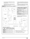
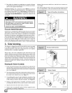
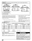
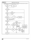
Figure 8 illustrates how to provide combustion and ventilation
air when two permanent openings, one inlet and one outlet, are
used.
a. One opening MUST commence within 12" of the floor
and the second opening MUST commence within 12" of
the ceiling.
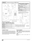
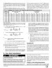
b. Size openings and ducts per Table 1.
c. Horizontal duct openings require 1 square inch of free
2
area per 2,000 BTUH (1,100 mm /kW) of combined input
for all gas appliances in the space (see Table 1).
d. Vertical duct openings or openings directly communicat-
ing with the outdoors require 1 square inch of free area
2
per 4,000 BTUH (550 mm /kW) for combined input of all
gas appliances in the space (see Table 1).
When one permanent outdoor opening is used, the opening
requires:
a. 1 sq. in of free area per 3,000 BTUH (700 mm2/kW) for
combined input of all gas appliances in the space (see
Table 1) and
b. not less than the sum of the areas of all vent connectors in
the _space.
G3