


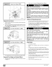

wiseto decreasemanifoldpressureand clockwiseto Operation Above 2000' Altitude
increase pressure.
NOTE: Adjustment screw cover MUST be replaced on gas control
valve before reading manifold pressure and operating furnace.
4,
5.
Set manifold pressure to value shown in Table 6 or Table 7.
When the manifold pressure is properly set, replace the ad-
justment screw cover on the gas control valve.
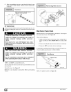
6. Remove jumper wire from thermostat connection on fan
board. Remove manometer connection from manifold pres-
sure tap, and replace plug in gas valve.
7. Check for leaks at plug.
Natural Gas Input Rating Check
The gas meter can be used to measure input to furnace. Check
with gas supplier for actual BTU content.
1. Turn OFF gas supply to all appliances other than furnace and
start furnace. Use jumper wire on R to W.
2. Time how many seconds it takes the smallest dial on the gas
meter to make one complete revolution.
Note: If meter uses a 2 cubic foot dial, divide results (seconds) by
two.
Refer to Example. The Example is based on a natural gas BTU
content of 1,000 BTU's per cubic foot.
Example
Natural Gas Time Per Cubic
BTU Content No. of Seconds Foot in BTU Per
Per Hour Hour
per cubic foot Seconds
1,000 3,600 48 75,000
1,000 x 3,600 + 48 = 75,000 BTUH
3. Remove jumper wire from R to W.
4. Relight all appliances and ensure all pilots are operating.
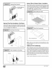
Orifice Sizing
NOTE: Factory sized orifices for natural and LP gas are listed in
the furnace Technical Support Manual.
Ensure furnace is equipped with the correct main burner orifices.
Refer to Table 6 or Table 7 for correct orifice size and manifold
pressure for a given heating value and specific gravity for natural
and propane gas.
FIRE, EXPLOSION, CARBON MONOXIDE
POISONING HAZARD.
Failure to follow these instructions exactly could
result in death, personal injury and/or property dam-
age.
This high-altitude gas-conversion shall be done by
a qualified service agency in accordance with the
Manufacturer's instructions and all applicable
codes and requirements, or in the absence of local
codes, the applicable national codes.
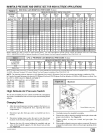
These furnace may be used at full input rating when installed at al-
titudes up to 2000'. When installed above 2000', the input must be
decreased 2% (natural) or 4% (LP) for each 1000' above sea level
in the USA. In Canada, the input rating must be derated 5% (natu-
ral) or 10% (LP) for each 1000' above sea level. This may be ac-
complished by a simple adjustment of manifold pressure or an
orifice change, or a combination of a pressure adjustment and an
orifice change. The changes required depend on the installation
altitude and the heating value of the fuel. Table 6 & Table 7 show
the proper furnace manifold pressure and gas orifice size to
achieve proper performance based on elevation above sea level
for both natural gas and propane gas.
To use the natural gas table, first consult your local gas utility for
the heating value of the gas supply. Select the heating value in the
first column and follow across the table until the appropriate eleva-
tion for the installation is reached. The value in the box at the inter-
section of the altitude and heating value provides not only the
manifold pressure but also the orifice size. In the natural gas tables
the factoy-shipped orifice size is in bold (42). Other sizes must be
obtained from service parts.
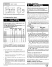
High Altitude Input Rate =
Nameplate Sea Level Input Rate x (Multiplier) [USA]
Elevation
2001'-3000'
3001'-4000'
4001'-5000'
5001'-6000'
6001'-7000'
7001'-8000'
High Altitude Multiplier
Natural Gas
0.95
0.93
0.91
0.89
0.87
0.85
LP Gas
0.90
0.86
0.82
0.78
0.74
0.70
* Based on mid-range of elevation.
_] 441 01 261302