


5,
6,
7.
Use ground joint unions and install a drip leg no less than 3"
long to trap dirt and moisture before it can enter gas control
valve inside furnace.
Provide a 1/8" NPT plugged tapping for test gauge connection
immediately up stream of gas supply connection to furnace.
Use two pipe wrenches when making connections to prevent
furnace gas control valve from turning.
NOTE: If local codes allow the use of a flexible gas appliance con-
nector, always use a new listed connector. Do not use a connector
which has previously served another gas appliance.
8. Flexible corrugated metal gas connector may NOT be used
inside the furnace or be secured or supported by the furnace
or ductwork.
9. Properly size gas pipe to handle combined appliance load or
run gas pipe directly from gas meter or LP gas regulator.
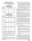
10. Install correct pipe size for run length and furnace rating.
11. Measure pipe length from gas meter or LP second stage regu-
lator to determine gas pipe size.
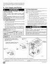
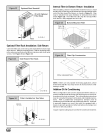
Right SideGas SupplyPiping (N8MP)
Gas line can be installed directly to the gas valve through the hole
provided in the right side of the cabinet. See Figure 12
Left Side Gas Supply Piping (N8MP)
Two(2) 90 ° street elbows or two(2) 90 ° standard elbows and
two(2) close nipples are required for left side gas supply. See
Figure 12.
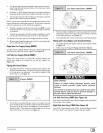
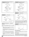
Piping with Street Elbows
1,
Assemble the elbows so that the outlet of one(l) elbow is 90 °
from the inlet of the other. The elbows should be tight enough
to be leak proof. An additional 1/4 turn will be required at the
end of step 2, see Figure 13.
iiiiiiiiiiiiiiiiiiiiiiiiiiiii_;!iiiiiiiiiiiiiiiiiiii!!iiiiii!!il;iiiiii!i¸iiiii!!iiiiiiiiiiiiiiiiiiiiiiiiiiiiiiiiiiiiiii;i;ii;!iiiiiiiiiii_i
2,
(_ 25-23-23c
Screw elbow assembly into gas valve far enough to be leak
proof. Position elbow assembly so that the inlet of the el bow is
at the top of the gas valve. An additional 3/8 turn will be re-
quired in step 3. Turn open end of inlet elbow to face the left
side of the furnace (1/4 turn), see Figure 14.
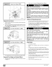
Gas Valve with Elbows (N8MP)
3. Turn assembly an additional 3/8 turn to position inlet near the
bottom back corner of the gas valve in line with gas opening
on left side of furnace, see Figure 15.
4. Gas supply line then can be run directly into opening of elbow.
Piping with Close Nipples and Standard Elbows
1. Assemble elbows and nipples similar to street elbows shown
in Figure 13.
2. Follow steps 2 through 4 Piping with Street Elbows.
Gas Valve with Elbows (N8MP)
25-24-96a-2
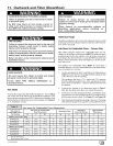
FIRE HAZARD
Failure to follow safety warnings exactly could
result in death, personal injury and/or property
damage.
Use wrench to hold furnace gas control valve when
turning elbows and gas line to prevent damage to
the gas control valve and furnace.
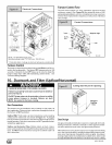
Left Side Gas Entry C8MP) (See Figure 16)
Pipe can be run directly to gas valve through the hole provided in
the left side of the cabinet.
Right Side Gas Entry C8MP) (See Figure 16)
Two (2) 90 ° street elbows or two (2) 90 ° standard elbows and two
(2) close nipples are required for right side gas supply,.
441 01 2613 02 [_