


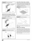

Optional Duct Standoff
Filter
20 x 25 Optional
Filter Rack
25-23-05-4
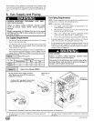
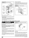
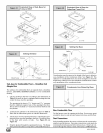
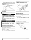
Optional Filter Rack Installation: Side Return
Center the filter rack on the side panel, flush with the bottom edge
of the furnace. Mark the fastening holes. Drill the fastening holes
in the side panel and fasten the filter rack in place with sheet metal
screws. See Figure 23 and Figure 24.
iiiiii¸i¸i¸i¸i¸iiiiii_¸I¸!iii!iii¸iiiiiiiiiiiii iiiiiiiiiiiiiiiiiiiii;ii;ii;ii;ii¸ii
Side Return Filter Rack
Filter
25-23-05-4a
iiiiiiiiiii ¸iiiiiiiiiiiiiiiiii!!ili;i!i!!!!!!!i!! i!iiiiiiiii;i
i_ Filters Installed on Two Sides
Using Two
Filter Racks
Filter
Filter
25-23-05-3
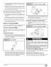
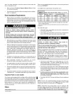
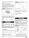
Internal Filter in Bottom- Return Installation
When installing a bottom-mounted filter inside the furnace, install
the filter clips on the edge of the bottom duct opening with the wider
end of the clips toward the blower, as shown in Figure 25. Clips
may be obtained from your distributor or fabricated from sheet
metal (Figure 26). Insert filter into side clips first and push filter
back until it is fully engaged into back clip.
Bottom Mounted Filter
Center Clip
sideto
25-24-18-1
11/4"
26 Ga, Galvanized Steel
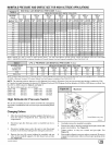
NOTE: If filters are only suitable for heating application, advise
homeowner that filter size may need to be increased if air condi-
tioning is added.
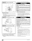
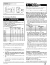
Addition Of Air Conditioning
When a refrigeration coil is used in conjunction with this furnace, it
must be installed on the discharge side of the furnace to avoid con-
densation in the heat exchanger. The coil installation instructions
must be consulted for proper coil location and installation proce-
dures. With a parallel flow arrangement, dampers must be
installed to prevent chilled air from entering the furnace. Ifmanual-
ly operated dampers are used, they must be equipped with a
means to prevent operation of either unit unless the damper is in
full heat or full cool position.
Copper or plastic tubing may be used for the condensate drain line.
441 O1 261302