


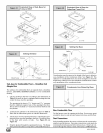

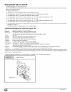
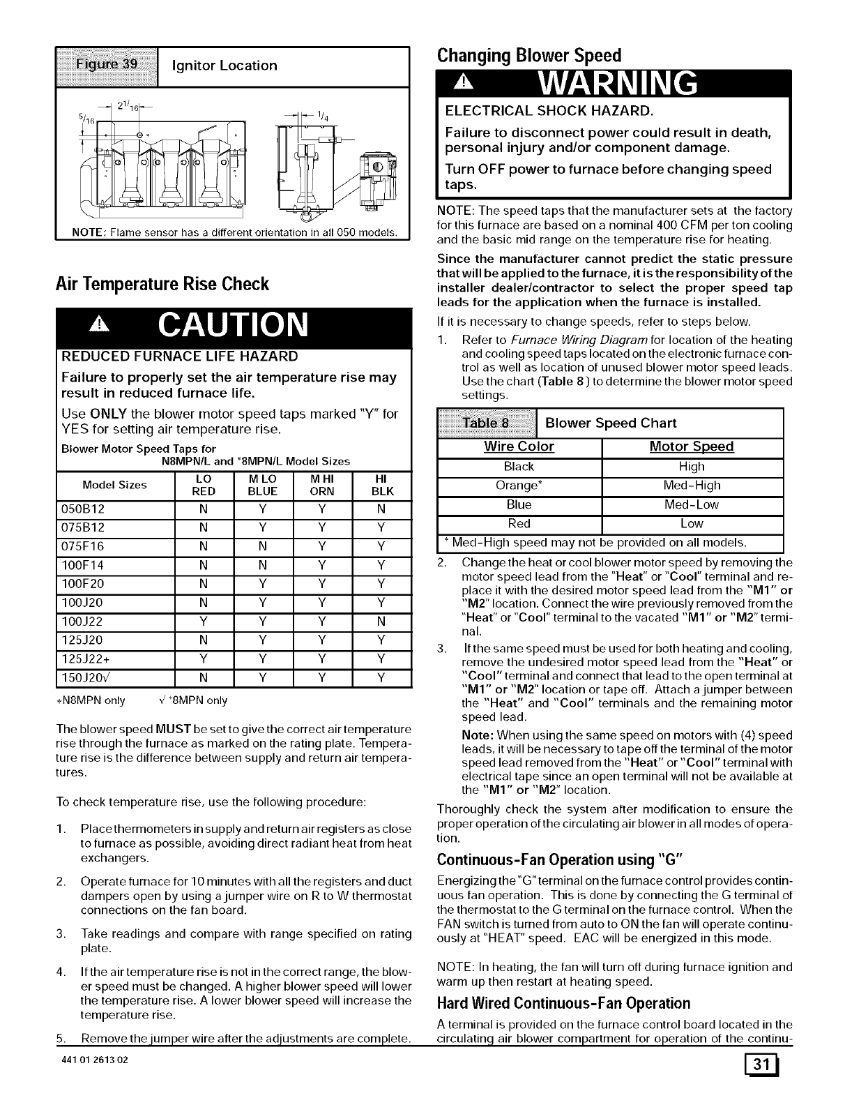
Ignitor Location
NOTE: Flame sensor has a different orientation in all 050 models.
Air TemperatureRise Check
REDUCED FURNACE LIFE HAZARD
Failure to properly set the air temperature rise may
result in reduced furnace life.
Use ONLY the blower motor speed taps marked "Y" for
YES for setting air temperature rise.
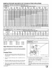
Blower Motor Speed Taps for
NSMPNtL and *8MPN/L Model Sizes
ModelSizes
050B12
075B12
075F16
100F14
100F20
100J20
100J22
125J20
125J22+
150J20{
+N8MPN only
LO
RED
N
N
N
N
N
N
Y
N
Y
N
{ _8MPNonly
M LO M HI HI
BLUE ORN BLK
Y Y N
Y Y Y
N Y Y
N Y Y
Y Y Y
Y Y Y
Y Y N
Y Y Y
Y Y Y
Y Y Y
The blower speed MUST be set to give the correct air temperature
rise through the furnace as marked on the rating plate. Tempera-
ture rise is the difference between supply and return air tempera-
tures.
To check temperature rise, use the following procedure:
1. Place thermometers in supply and return air registers as close
to furnace as possible, avoiding direct radiant heat from heat
exchangers.
2. Operate furnace for 10 minutes with all the registers and duct
dampers open by using a jumper wire on R to W thermostat
connections on the fan board.
3,
4.
Take readings and compare with range specified on rating
plate.
If the air temperature rise is not in the correct range, the blow-
er speed must be changed. A higher blower speed will lower
the temperature rise. A lower blower speed will increase the
temperature rise.
5. Removethe ULU.m._erwire after the adiustments are complete.
441 01 261302
Changing Blower Speed
ELECTRICAL SHOCK HAZARD.
Failure to disconnect power could result in death,
personal injury and/or component damage.
Turn OFF power to furnace before changing speed
taps.
NOTE: The speed taps that the manufacturer sets at the factory
for this furnace are based on a nominal 400 CFM per ton cooling
and the basic mid range on the temperature rise for heating.
Since the manufacturer cannot predict the static pressure
that will be applied to the furnace, it is the responsibility of the
installer dealer/contractor to select the proper speed tap
leads for the application when the furnace is installed.
If it is necessary to change speeds, refer to steps below.
1. Refer to Furnace Wiring Diagram for location of the heating
and cooling speed taps located on the electronic furnace con-
trol as well as location of unused blower motor speed leads.
Use the chart (Table 8 ) to determine the blower motor speed
settings.
I Blower Speed Chart
Wire Color Motor Speed
Black High
Orange* Med- High
Blue Med-Low
Red Low
* Med-High speed may not be provided on all models.
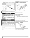
2. Change the heat or cool blower motor speed by removing the
motor speed lead from the "Heat" or "Cool" terminal and re-
place it with the desired motor speed lead from the "M1" or
"M2" location. Connect the wire previously removed from the
"Heat" or "Cool" terminal to the vacated "M1" or "M2" termi-
nal.
3. If the same speed must be used for both heating and cooling,
remove the undesired motor speed lead from the "Heat" or
"Cool" terminal and connect that lead to the open terminal at
"MI" or "M2" location or tape off. Attach a jumper between
the "Heat" and "Cool" terminals and the remaining motor
speed lead.
Note: When using the same speed on motors with (4) speed
leads, it will be necessary to tape off the terminal of the motor
speed lead removed from the "Heat" or "Cool" terminal with
electrical tape since an open terminal will not be available at
the "M1" or "M2" location.
Thoroughly check the system after modification to ensure the
proper operation of the circulating air blower in all modes of opera-
tion.
Continuous-Fan Operationusing "G"
Energizing the"G" terminal on the furnace control provides contin-
uous fan operation. This is done by connecting the G terminal of
the thermostat to the G terminal on the furnace control. When the
FAN switch is turned from auto to ON the fan will operate continu-
ously at "HEAT" speed. EAC will be energized in this mode.
NOTE: In heating, the fan will turn off during furnace ignition and
warm up then restart at heating speed.
Hard Wired Continuous-Fan Operation
A terminal is provided on the furnace control board located in the
circulatinq, air blower compartment for operation of the continu-