


area. It is often advisable to route the return air ducts under the Filters are not supplied with these furnaces, but can be purchased
floor or through the attic, from your distributor.
• Refer to furnace Technical Support Manual (Blower Data)
for air flow information.
• Size ductwork to handle air flow for heating (and air condition-
ing if so equipped).
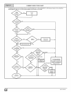
Duct Installation Requirements
When a furnace is installed so that supply ducts carry air cir-
culated by the furnace to areas outside of the space contain-
ing the furnace, the return air shall also be handled by duct(s)
sealed to the furnace casing and terminating outside the
space containing the furnace.
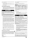
CARBON MONOXIDE POISONING HAZARD.
Failure to follow safety warning exactly could
result in death, personal injury, and/or component
damage.
Install cooling coil on furnace discharge. Cool air
passing over heat exchanger could cause conden-
sate to form resulting in heat exchanger failure.
• When the furnace is used with a cooling unit, the furnace shall
be installed parallel with or on the upstream side of the cooling
unit to avoid condensation in the heating element.
With a parallel flow arrangement, the da topers or other means
used to control flow of air shall be adequate to prevent chilled
air from entering the furnace. Chilled air going through the fur-
nace could cause condensation and shorten furnace life.
Dampers (purchased locally) can be either automatic or
manual. Manually or automatically operated dampers MUST
be equipped with a means to prevent furnace and air condi-
tioning operation, unless damper is in the full heat or cool posi-
tion.
• Installation of locking-type dampers is recommended in all
branches, or in individual ducts to balance system's air flows.
• Non-combustible, flexible duct connectors are recom-
mended for return and supply connections to furnace.
• If air return grille is located close to the fan inlet, install at least
one 90 ° air turn between fan and inlet grille to reduce noise.
• Ductwork installed in attic or exposed to outside temperatures
requires a minimum of 2" of insulation with outdoor type vapor
barrier.
• Ductwork installed in an indoor unconditioned space requires
a minimum of 1" of insulation with indoor type vapor barrier.
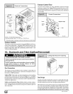
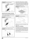
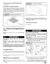
Inspection Panel on some models
For a furnace not equipped with a cooling coil, the outlet duct shall
be provided with a removable access panel. This opening shall be
accessible when the furnace is installed and shall be of such a size
that the heat exchanger ca n be viewed for possible openings using
light assistance or a probe can be inserted for sampling the air
stream. This access cover shall be attached in such a manner as
to prevent air leaks.
Filters
A filter MUST be used.
441 01 2613 02
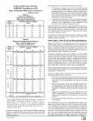
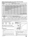
See Table 4 for required high-velocity filter sizes.
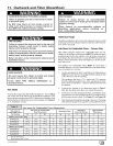
iiiiiiiiiiiiiiiiiil_i!!!!:_i;:ii;i;i;i;i;i;i;_;:_:_:_:_i_iiiiiiiiiiiiiiiiiiiii_i_!!i¸!I¸iiiiiiiiiiiii!iiiiiiiiiii
Cabinet
Width
151/2
191/2
223/4
High-Velocity Air Filter Sizes (max.600FPM)
Internal Filter External Filter Rack
Bottom Bottom Side+
14X25 14X25 14X25 or 16X25
16X25" 16X25" 16X25"
20X25" 20X25" 16X25"
Greater than 1600 CFM requires both (left and right) side return filter
racks in upflow position.
+ Side return air duct(s) is not permitted with horizontal or downflow furnace
installation,
Use either filter type:
• Washable, high-velocity filters are based on a maximum air
flow rating of 600 FPM.
• Disposable, low velocity filters are based on a maximum air
flow of 300 FPM when used with external filter grille.
RISK OF REDUCED FURNACE LIFE
Failure to follow these Caution may result in
premature furnace component failure.
Use of excessively dirty and/or restrictive air filters
may increase furnace operating temperatures and
shorten the life of the furnace.
Filters specified for the furnace are rated at a maximum
of 600 FPM air velocity and sized for the furnace's
airflow rate. Replacement filters must be of equivalent
type, size, and rating except as described below.
Disposable, low-velocity filters may be used to replace
washable, high-velocity filters, providing they are sized
for 300 FPM or less.
I
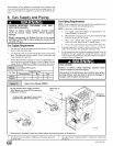
• The furnaces with 1600 or less CFM rating use a 16" x 25"
high-velocity filter. On these models the filter may be
mounted internally for bottom return or a filter and rack may
be mounted externally for bottom return.
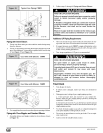
• The furnaces with greater than 1600 CFM require that both
(left and right) side returns are used. Two side return filters
and racks are required. Filter racks must be mounted exter-
nally. See Figure 24.
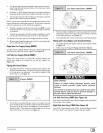
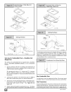
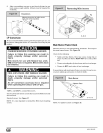
• If return air must be on one side only, an optional 20" x 25"
filter standoff rack kit can be used. (See Figure 22.) For bot-
tom return, an internal filter can be used or a filter rack kit can
be mounted externally.
• See pages 40 & 46, CirculatorAirBIowerData for additional
data.
NOTE: The 20" x 25" standoff side filter rack gives more filter area
but does not provide more air. See Figure 22. To achieve 2000
CFM 2 side returns are still needed. See Figure 24.
NOTE: Disposable low-velocity filters may be replaced with
washable, high-velocity filters. Washable, high-velocity filters can
be replaced ONLY with same type and size filter unless low-veloc-
ity filters meet the minimum size areas for 300 FPM or less.