


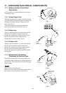

10-4-2. Outdoor Fan Motor
This outdoor DC fan motor contains an internal control PCB. Therefore, it is not possible to measure the coil
resistance, and the following procedure should be used to check the motor.
To perform diagnosis, follow the instructions in "Checking the Outdoor Unit" on the previous page and set the
outdoor unit to Test Run mode (compressor ON, outdoor fan motor ON).
[Trouble symptom 1] The fan does not stop when the outdoor unit stops. Outdoor unit controller trouble
[Trouble symptom 2] The fan motor does not rotate when the outdoor unit is operating.
(Diagnostic procedure)
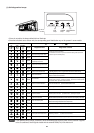
* Disconnect the motor connectors and measure the voltage at the DC motor connectors on the outdoor
unit controller (3 locations).
(Diagnostic results)
All of the above measured values are normal. Fan motor trouble (Replace the motor.)
Any one of the above measured values is not normal. Outdoor unit controller trouble
(Replace the controller .)
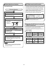
(Reference) DC motor connector pin arrangement
Pin 1: Vs (white)
Pin 2: Not used
Pin 3: Not used
Pin 4: Gnd (black)
Pin 5: Vcc (red)
Pin 6: FG (blue)
Pin 7: Vsp (yellow)
[Trouble symptom 3] Motor rotates for some time (several seconds), but then quickly stops, when the outdoor
unit operates.
(There is trouble in the system that provides feedback of motor rotation speed from the
motor to the outdoor unit controller.)
[Trouble symptom 4] Fan motor rotation speed does not change during outdoor unit operation.
[Trouble symptom 5] Fan motor rotation speed varies excessively during outdoor unit operation.
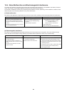
(Remedy for symptom 3 to 5)
It is not possible to identify whether the trouble is outdoor unit controller trouble or motor trouble.
Therefore, first replace the outdoor unit controller, then (if necessary) replace the DC motor.
Important:
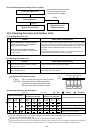
(A) Turn OFF the power before connecting or disconnecting the motor connectors.
(B) When performing voltage measurement at the outdoor controller connector for (3) in the table
below, the DC motor will trip and voltage output will stop approximately 10 seconds after
operation is started. For this reason, to measure the voltage again, first turn OFF the outdoor
unit power, then follow the instructions in "Checking the Outdoor Unit" and again set the unit to
Test Run mode.
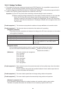
(1) Vs-Gnd: Between pin 1 and pin 4
(2) Vcc-Gnd: Between pin 5 and pin 4
(3) Vsp-Gnd: Between pin 7 and pin 4
Measurement location
DC 230 V or more
DC 14 V or more
After fluctuating 4 times between DC 1.0 to 4.3 V
(1 sec. ON) and DC 0 V (1 sec. OFF), the DC
motor trips.
Normal value
47