


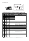
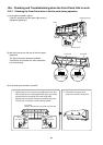

(2) If the self-diagnostics function fails to operate
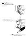
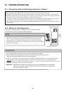
10-3. Checking the Indoor and Outdoor Units
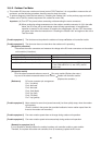
(1) Checking the indoor unit
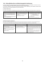
(2) Checking the outdoor unit
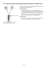
(3) Checking the serial communications
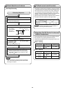
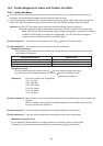
Using the TEST/T-RUN terminals
Check the indoor unit.
Is the fuse blown?
ControlNo. Check items (unit operation)
Replace the controller.
Replace the circuit
board or the fuse.
No indicators illuminate and the
indoor fan does not rotate.
Check the power voltage.
T-RUN : Test run (compressor and fan motor turn ON).
TEST/MV : Compresses time to 1/60th (accelerates
operation by 60 times faster than normal).
Fully opens the electric expansion valve.
Press EMERGENCY OPERATION button
of main unit controller, or start operation
using the remote controller.
If there are no problems with the above, then check the outdoor unit.
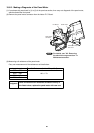
1
Press and hold the TEST RUN button
on the main unit controller until the buzzer
sounds 1 time.
2
The rated voltage must be present between inter-unit wirings 1 and 2.
Connect a 5 kohm resistor between inter-unit cables 2 and 3. When the
voltage at both ends is measured, approximately 12 to 15 V DC must
be output and the multimeter pointer must bounce once every 8
seconds.
Or instead of measuring the voltage, you can insert an LED jig and
check that the LED flickers once every 8 seconds.
ControlNo. Check items (unit operation)
Apply the rated voltage between outdoor
unit terminals 1 and 2.
If there are no problems with the above, then check the indoor unit.
Turn the power OFF before performing short circuiting work.
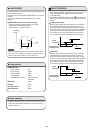
During the self-diagnostics check, the check results are the first indication when the TEST RUN button is pressed until the buzzer
sounds 1 time, after the power supply is ON.
So that the check can be made quickly, indicators blink at first communication after power ON.
Before performing the above checks, press the ON/OFF operation button of indoor unit or remote controller to operate the air conditioner,
and check that AC 220 to 240V is output to terminals 1 and 2. If it is not output, there is a failure related to the indoor unit power.
1 The control panel LED (red) must illuminate.
Short-circuit the outdoor unit COM terminal
to the T-RUN terminal.
2
The compressor and fan motor must turn ON about 5 seconds later
after the terminals are shorted.
Normal
Blown
TEST/MV T-RUN terminals
TEST/MV T-RUN COM
Circuit
board
Probable location of malfunction
Indoor unit circuit board failure
Outdoor unit circuit board failure
Failure (open circuit, contact failure, etc.)
in the inter-unit wirings
Outdoor unit circuit board failure
Short-circuit terminals 2 and 3 on
the outdoor unit terminal plate.
Short-circuit terminals 2 and 3 on
the indoor unit terminal plate.
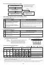
Initial self-diagnostics
Control 1 Control 2
....
OFF
....
Blinking
....
Illuminated
Ion
( 3 )
Timer
( 2 )
Operation
( 1 )
Ion
( 3 )
Timer
( 2 )
Operation
( 1 )
Ion
( 3 )
Timer
( 2 )
Operation
( 1 )
45