


English _ 7
PRODUCT INTRODUCTION
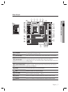
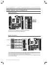
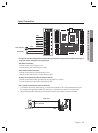
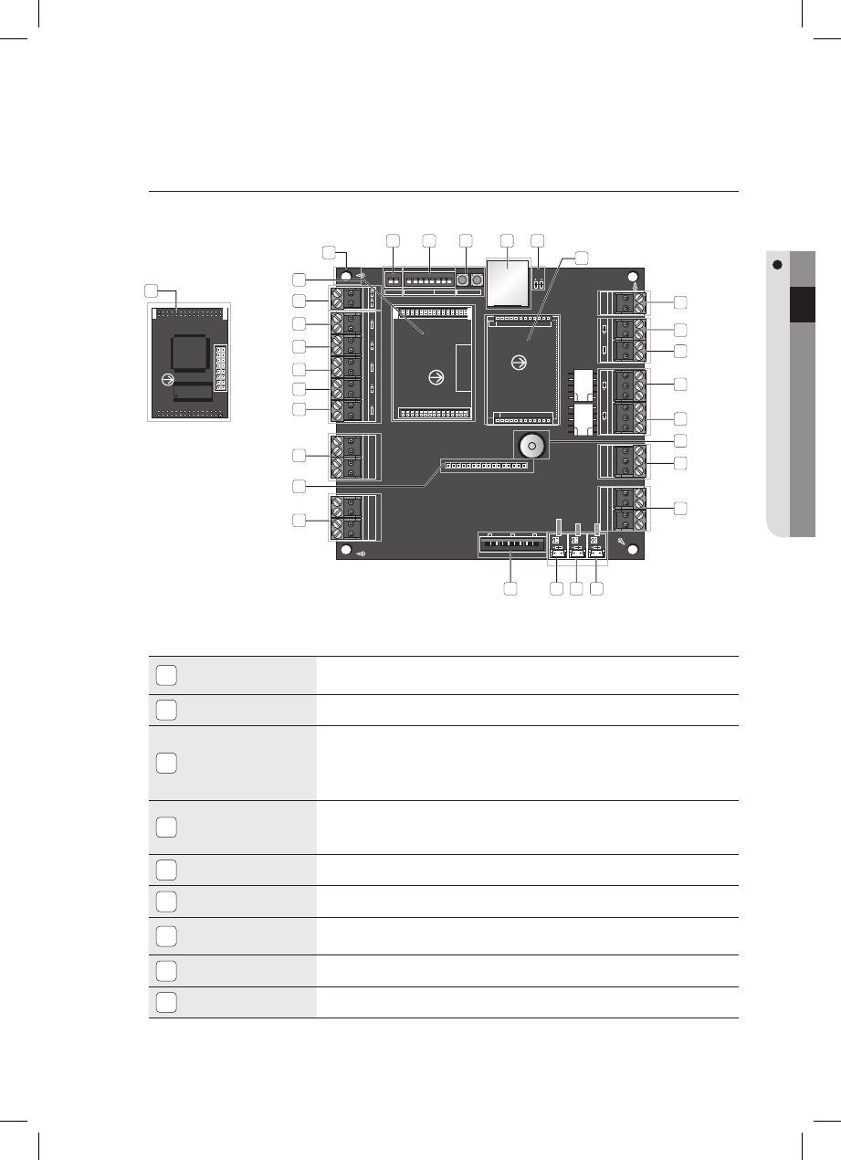
Main Board
1
Fixing Hole
Used to attach SSA-P102 to the closure using a metal supporter. (Ensure that you use
the metal supporter to prevent the EMI.)
2
2Pin DIP Switch
Used to set the type of a connected reader to either 26bit Wiegand or 34bit Wiegand.
3
8Pin DIP Switch
The device address and communication speed specifi ed by the applicable switch should
be consistent with those of the computer that is used for communications.
(Address Setting: Pin 1 to Pin 5 of the DIP Switch, Communication Speed: Pin 6 to Pin 8
of the DIP Switch)
4
System Initialize Switch
Pressing both of the switches at the same time for about 2 seconds will sound
initialization ready beep. Releasing both switches will stop the beep, and restarts the
system after the initialization.
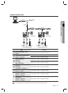
5
RJ-45
Connect the LAN cable for TCP/IP communications.
6
LED
Indicates the state of the LAN communications.
7
RL#1, RL#2
Ports where the buzzer control line or the LED control line of the reader is connected to
display the operation status of Relay 1 or Relay 2.
8
Input #5
Input Port: The fl ashing LED indicator denotes that a signal is sensed by the port.
9
Input #4
Input Port: The fl ashing LED indicator denotes that a signal is sensed by the port.
1
13
30
7
8
9
10
11
12
15
18
16
19 27 28 29
14
20
21
22
23
24
17
25
26
2 3 4 5 6