


English _ 13
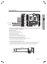
INSTALLATION AND EXTERNAL CONNECTION
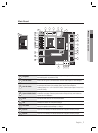
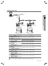
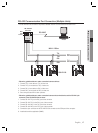
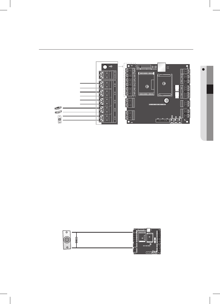
Input Connection
- The Input #1 and Input #2 ports have the Exit button and the Door Contact Sensor installed, while Input #3
to Input #5 can be confi gured to your preference.
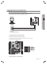
- Exit Button Connection
Connect one line of the Exit button to IN 1.
Connect the other line of the Exit button to GND.
- Door Contact Sensor Connection
Connect one line of the Door Contact Sensor to IN 2.
Connect the other line of the Door Contact Sensor to GND.
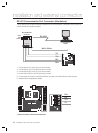
- Auxiliary Device Connection (AUX #3, AUX #4, AUX #5)
Connect one line of the auxiliary input device to any one of IN3, IN 4, and IN 5.
Connect the other end of the auxiliary input device to GND.
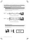
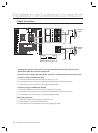
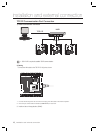
- 2.2k
Ω Resistor Connection for Short-Circuit Check
To enable the short-circuit check function, you must have connected a 2.2KΩ resistor between the input line
(ex: orange) and the ground line (GND). First, specify if you check each input device for any short circuit.
Using the input port/DIP switch test, you can check if the short-circuit resistor is properly connected.
PUSH
Input Device
2.2
KΩ
Resistor
Input Line
GND
1.
2.
PUSH
Door Contact
Exit Button
GND
INPUT #5
GND
INPUT #4
GND
INPUT #3
GND
INPUT #2
GND
INPUT #1