


SECTION 3: CRITICAL CONSIDERATIONS
3
SECTION 3: CRITICAL CONSIDERATIONS
3.1 Basic Information
The CTUD heater that forms the heating section of
the DualAir
®
unit has an automatic ignition burner
and may be operated as fully modulating or ON/OFF
operation.
The standard unit has the air flow from left to right
when viewed from the controls side.
A special order version with the opposite air flow is
available where the combustion air intake and flue
will be at the front of the unit.
3.2 Location and Suspension
All models:
• Must be installed indoors.
• Must be installed in a level position.
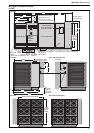
• May be mounted on the floor or on a shelf of
non-combustible material. (See Page 5, Section
4 and Page 9, Figure 3 for support points)
• May be suspended from above (See Page 9,
Figure 3), on the floor, or from wall brackets of
sufficient strength to support the DualAir
®
unit as
listed in the Dimension Data Table on Page 6,
Section 4.2. Drop rods must be a minimum of 12
mm diameter mild steel. Six suspension points
are located on top of the DualAir
®
unit.
• Must be installed in a manner which allows the
hinged door to be fully opened to provide access
to all serviceable components.
3.3 Minimum Required Installation Clearances
Clearances around the DualAir
®
unit and flue must
be as indicated on Page 4, Figure 2, Page 10,
Figure 4 through Page 12, Figure 8 to ensure
access for servicing, and correct operation.
3.4 Clearances to Combustibles
Clearances must be as indicated on Page 4, Figure
2. If no clearances to combustibles are indicated,
then installation clearances apply.
3.5 Ventilation
It is important to ensure that there is adequate air
circulation around the DualAir
®
unit to supply air for
combustion, ventilation and distribution in
accordance with local and national codes.
3.6 Gas Supply
It is important that the gas supply pipe is sized
correctly to provide the inlet pressure as stated on
the heater data plate. The gas supply pipe and
electrical connections must not support any of the
heater's weight.
3.7 Electrical Supply
A permanent 400v 3ø 50Hz electrical supply is
required at the main electrical terminals. The heater
also requires suitable energy controls in accordance
with Section 10.
3.8 Flue
Choose a location to allow for the proper alignment
of the flue. Each DualAir
®
unit must be fitted with an
individual and correctly sized sealed flue system
(See Page 10, Section 6).
No other appliance may be connected to the flue.
For room-sealed installation, the air intake must be
the same size sealed system and the flue/air intake
must terminate at an approved concentric wall or
roof terminal.
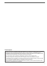
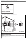
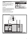
3.9 Coil Condense Drain
The cooling coil must be fitted with a suitable
condense drain. The condense pipe work should be
in plastic or copper piping in accordance with the
latest revision of applicable standards and local and
national codes.
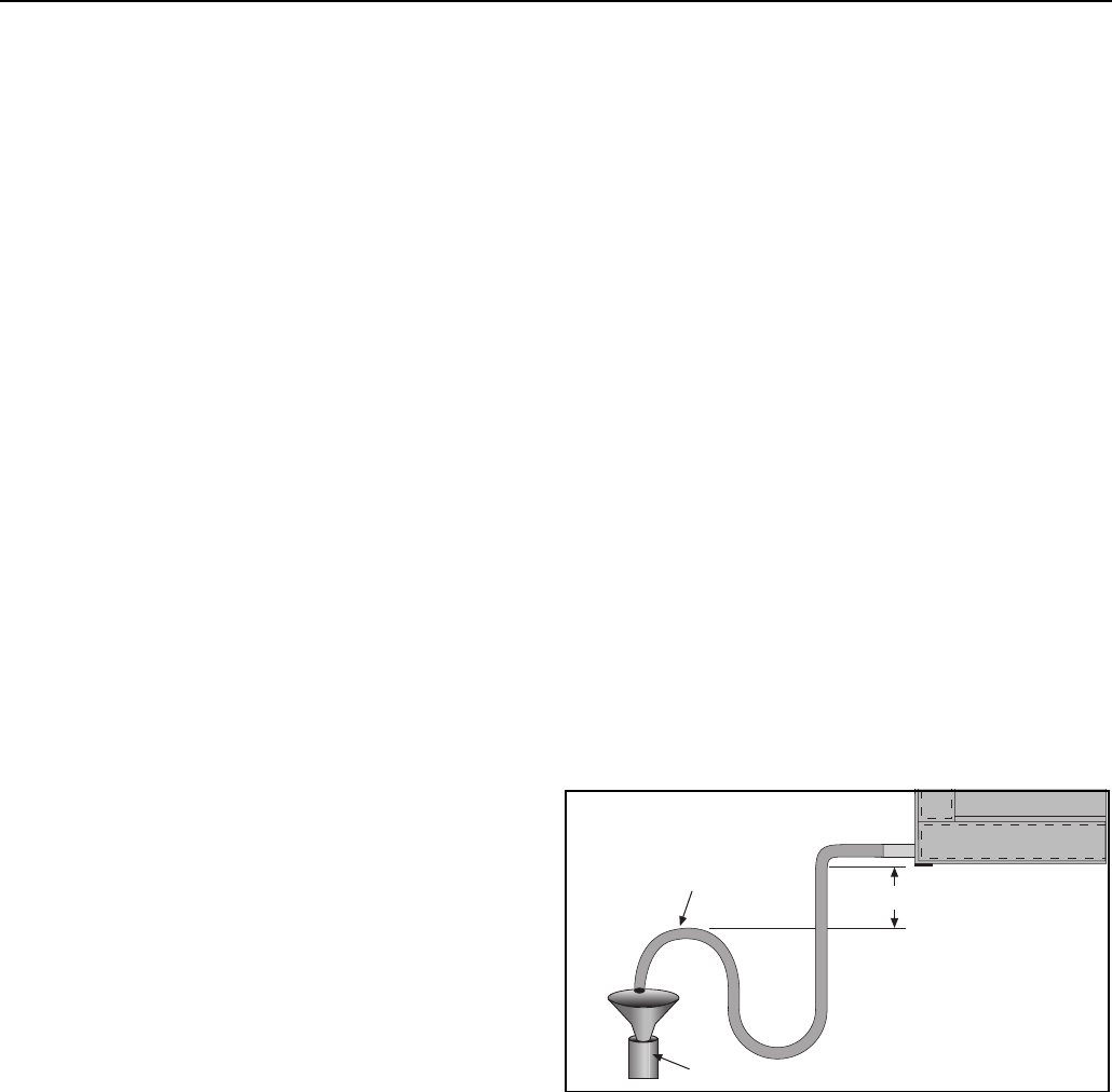
Figure 1: Condense Drain
Failure to install the condense drain correctly may
cause water carry over into the fan compartment,
which may then escape and cause property
damage.
100 mm min.
Install to Suitable Drain
Drain to Open Funnel
Trap must be filled with
water to be effective and
prevent air being drawn
backwards into the drip tray.