


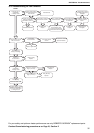


SECTION 16: REMOVAL AND REPLACEMENT PARTS
41
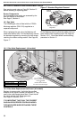
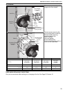
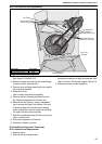
16.6 Cooling Coil Safety Devices
16.6.1 Cooling Coil Frost Thermostat
The sensing element for this device is inserted into
the pocket of the cooling coil situated through the
access hole in the coil cover.
The frost thermostat has two settings marked as set
point with an arrow head and "diff". The control
should be set at 5° C with a 1° C differential.
To replace, remove screw and pull off knob.
Remove cover. Disconnect wires.
Pull the sensing element out of the pocket in the coil.
Replace in reverse order.
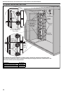
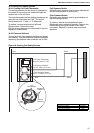
16.6.2 Pressure Switches
The coil and dirty filter pressure switches are preset
and different. They are differential pressure switches
measuring the pressure loss across the coil or filter.
Coil Pressure Switch
(Normally open contact) used to prove adequate air
flow for safe operation of cooling coil.
Filter Pressure Switch
(Normally open contact) used to give indication of
filter becoming blocked.
To replace, remove coil compartment cover.
Disconnect wires noting their position. Remove the
flexible tubing noting the position of the tube
connection. Replace in reverse order and check
operation.
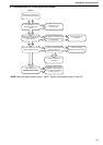
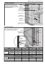
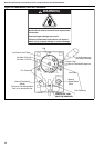
Figure 18: Cooling Coil Safety Devices.
Coil Frost Thermostat
set at 5°C with 1°C diff.
Filter
White
White
Red
Red
Coil Pressure Switch
set at 0.57 mbar (.23 in wc)
Filter Pressure Switch
set at 1.17 mbar (.47 in wc)
Negative
Pressure
Positive
Pressure
Set
Point
N.O
Connections
Description Part Number
Coil Pressure Switch 90439801
Filter Pressure Switch 90439804
Coil Frost Thermostat K018