


SECTION 16: REMOVAL AND REPLACEMENT PARTS
37
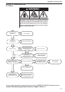
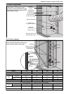
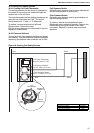
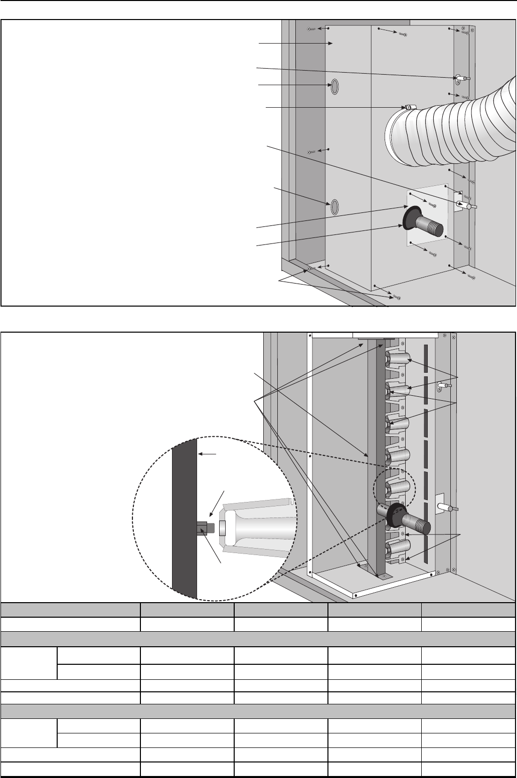
16.2 Burner Compartment
16.2.1 Burner Injectors
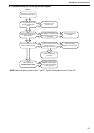
Remove flexible
air duct from spigot
Remove
access plate
Remove screws and
pull off burner cover
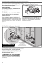
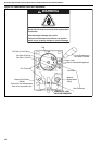
Viewing port
for flame probe
Viewing port
for ignition electrode
Flame probe
Burner
compartment
cover
Rubber Seal
Ignition electrode
The burner compartment is a sealed
compartment. Following any work,
re-seal the compartment with the gas
pipe rubber seal fully in place and all
screws fitted and tight.
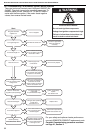
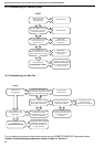
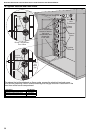
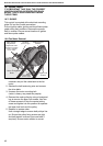
Remove manifold
screws and pull
out manifold
Manifold
Burners
Injectors
Burner
screws
Burner
venturi
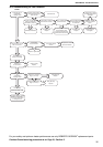
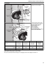
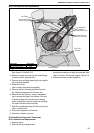
Unscrew
Injectors
Manifold
Marking
Ensure gas tight fitting of injectors.
Ensure correct alignment with burners.
Ensure all pipe joints are gas tight.
75 90 100 115
12 14 15 17
mm dia 2.71 2.71 2.71 2.71
in dia 0.1067 0.1067 0.1067 0.1067
36 36 36 36
91930036 91930036 91930036 91930036
mm dia 1.51 1.51 1.51 1.51
in dia 0.0594 0.0594 0.0594 0.0594
53 53 53 53
91930053 91930053 91930053 91930053
Marking
RG P/N
Injector
Size
Injector Quantity
LPG Gas Propane (G31) and LPG Gas Butane (G30)
MODEL
Injector
Size
Marking
RG P/N
Natural Gas (G20) and (G25)