


SECTION 10: WIRING AND ELECTRICAL INFORMATION
17
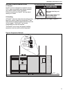
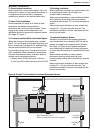
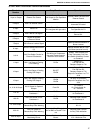
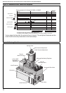
10.3 DAT Main Circuit Board Terminal Identification
Terminal
Number
Use Relay/Function Operation
1 Input or Output External Fan Control
Input for Remote Fan Opera-
tion Output for Fan Operation
Monitor
Optional - Main Fan Runs from
External Control
2 Output 230 V to external control
230 V 50 Hz supply of external
thermostat or control
3 Input Burner On
Burner Fires.
R1 energizes with gas valve
Burner Operates.
Fan Operates via R1
4 Output 230 V Burner ON Signal
Optional Remote Indication of
Burner ON.
5 Output
Neutral for Signals
& External Control
7 Output 230 V Burner Lockout Signal
Optional Remote Indication of
Burner Lockout
8 Input
Burner Lockout Reset from N
(5)
Optional Remote Burner Lock-
out Reset (must be from N)
9 & 10
Volt Free Safety Circuits for
External Condensers
Site Wiring to Condensers
Normally Closed Controls
Break on Fault Position
DualAir
®
units contains Coil
Frost Thermostat, Coil Pres-
sure Switch & Auxiliary Contact
on Contactor
11 Input
230 V 1st Stage of Cooling
(Free Cooling)
R2 On
Burner OFF
Fan ON from R2
Dampers Output to T16
12 Input
230 V 2nd Stage of Cooling
Cooling Coil Stage 1
R2 OFF
R3 ON
Burner OFF
Fan ON from R3
Dampers Output to T15
Output to Condenser 1 at T17
& 18
13 Input
230 V 3rd Stage of Cooling
Cooling Coil Stage 2
R3 ON
R4 ON
All input 12 Operations
Output to Condenser 2 at T19
& 20
14, 15 & 16 Output
230 V Output for Optional
Damper
From R2
14 = Neutral
15 = Recirculated Air
16 = Fresh Air
17 & 18
Volt Free Control Circuit
Condenser 1
R3 ON Normally Open Contact
for Condenser 1
19 & 20
Volt Free Control Circuit
Condenser 2
R3 ON
R4 ON
Normally Open Contact
for Condenser 2
21 & 22 Output
230 V Output to
Remote Dirty Filter Warning
21 = L
22 = N
23 & 24
Volt Free Output to
Remote Dirty Filter Warning
Alternative Dirty Filter Indica-
tion for BMS or DualAir
®
Con-
trol
Normally Open Contact
for Dirty Filter Indication
25 & 26 Input
0 - 10 V DC Input for
Modulating Burner
T3 Must Be Live to Operate
Burner
0 V = Minimum Fire
10 V = Maximum Fire