


DUALAIR
®
HEATING AND COOLING UNITS INSTALLATION OPERATION AND SERVICE MANUAL
16
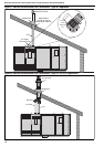
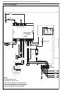
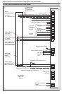
SECTION 10: WIRING AND ELECTRICAL INFORMATION
10.1 Electrical Supply
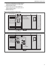
All heater models need a constant 400 V 50 Hz 3 ø
supply connected to terminals L
1
,L
2
, L
3
, N & Earth.
Polarity "L
1
& N" must be correct. The voltage
between neutral and earth should be 0 and never
exceed 15 volts.
All heaters and controls must be correctly earthed.
All external wiring must comply with the relevant
local codes. Wire specification H05VV-F.
External controls must have a constant 230 V 50 Hz
1 Ø supply.
An isolator with a contact separation of at least
3 mm on all poles must be installed adjacent to, but
not attached to, the DualAir
®
unit to disconnect all
supplies to the heater and any remote control.
The final connection to the heater should be made
by flexible cable or conduit to the main terminal
block in the control section using 1 mm
2
cable on all
models.
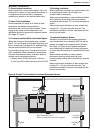
All cables entering through the top of the heater
should be routed via the metal shield to prevent
inadvertent contact with the flue.
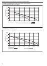
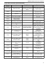
Models .............................................Fuse Size
DAT 75 & 90..................................................... 5 A
DAT 100 & 115 ................................................10 A
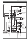
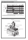
10.2 Remote Control
Roberts Gordon markets a dedicated DualAir
®
control that will operate all the available features of
the unit.
The DualAir
®
unit requires a 230 V remote control to
provide a time control and multistage heating/
cooling temperature control. See Page 20, Section
10.6.
To operate the modulating gas burner, a further
input of 0-10 V DC is required with 0V giving
minimum fire and a 10V giving full fire, wired in
screened cable (Belden 8451 or equivalent).
10.2.1 Remote Frost Thermostat
When required, connect to terminals 2 and 3 in the
main terminal block.
Locate within the heated space adjacent to the most
vulnerable equipment that requires protection.
See Page 17, Section 10.3 through Page 18, Section
10.4.
10.2.2 Remote Fan Controls
The fan will operate automatically.
A switch or control wired between terminals 2 & 1 in
the terminal block will allow external control of the
fan(s).
The fan may be operated continuously from an
external control, with the burner/cooling cycling on
and off.
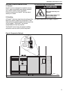
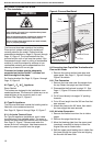
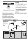
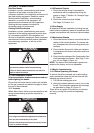
WARNING
Electrical Shock Hazard
Disconnect electrical power before servicing.
Failure to follow these instructions can result in
death or electrical shock.