


DUALAIR
®
HEATING AND COOLING UNITS INSTALLATION OPERATION AND SERVICE MANUAL
14
SECTION 8: OPTIONAL HEATER CONFIGURATIONS
8.1 Distribution Duct
DualAir
®
units are designed to be connected to
distribution and air inlet ducting.
It is recommended that flexible duct connectors and/
or attenuators are used to reduce duct born noises.
It is recommended that the inlet ducting is arranged
with both fresh air and recirculating air dampers to
take advantage of the "free cooling" stage provided.
Distribution ducting must be insulated to prevent
heat gain during cooling mode.
The air flow must be in the direction as stated for the
version being installed with the heater at the
discharge end.
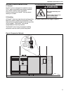
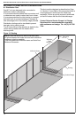
The duct must be designed as described on Page
14, Section 8.1 and Figure 10 to ensure that there is
a homogenous air flow across the whole heat
exchanger. Failure to provide a properly distributed
air flow will reduce the life of the heat exchanger.
Contact Roberts-Gordon Europe Ltd. Design
Department for recommendations regarding
duct resistance and design. Tel: +44 (0) 121 506
7700
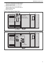
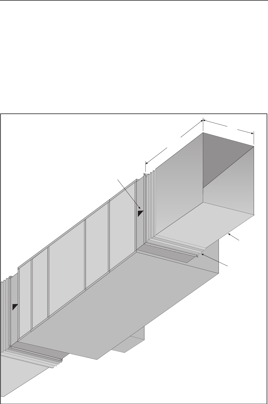
Figure 10: Ducting
Dimension
X
*Minimum-
Twice
Dimension
X
Airflow Indicator
Flexible Flange
Ducting
NOTE: Duct size will be full size of inlet and outlet.
All joints between the heater and duct work should be
made as air tight as possible.
*Inlet Duct Minimum Dimension same as Outlet Duct
Minimum Dimension