


ROBERTS GORDON
®
BH-SER I ES SUBMITTAL SHEET
© 2004 Roberts-Gordon
BEFORE IN STALLATION AND OPERATION OF HEATING EQUIPMENT, READ AND U NDERSTAND THE INSTALLATION, OPERATION AND SERVICE MANUAL.
APPLICATION S, ENGINEERING AND DETAI LED GUID ANCE ON SYSTEMS DE SIGN, INSTALLATION AND PRODUCT PERFORMANCE IS AVAI LABLE UPON REQUEST. ROBERTS GORDON
®
PRODUCTS ARE TO BE
INSTALLED ONLY IN ACCORDANCE WI TH L OCAL LAWS, CODES AND REGULATIONS, AND ONLY BY A CONTRACTOR QUALIFIED I N THE INST ALLAT ION AND SERVICE OF GAS-FIRED HEATING EQUIPMENT.
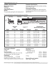
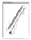
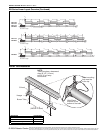
BH-SERIES ASSEMBLY OVERVIEW
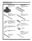
Major Component Descriptions
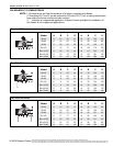
Burner with Tube Gasket
Must be installed with the
flame observation window
facing down.
Refle ctor (Aluminum or
Stainless Steel)
Alternate overlap as shown on
overview. Minimum overlap is
7” (18 cm).
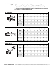
Tube and Reflector Hanger
with Clamp Package
Position this hanger no more
than 4” (10 cm) away from
the burner.
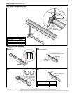
Coupling Assembly with Lock
Reflector End Cap
Punch out center section to
accommodate heat exchanger
tube.
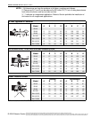
Tube and Reflector Hanger
Suspend system from these
hangers.
Flex Gas Line with
Shut Off Cock
Tube
Hot Rolled or Heat Treated
Aluminized Tube supplied in
10’ (3 m) lengths.
Burner Tube
Supplied in 10
' (3 m) lengths.
Burner tube is always the first
tube after the burner.
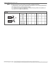
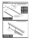
Reflector Support Strap &
Wire Form
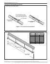
Turbulator
Turbulator must be installed in the
last standard section of tube.
Turbulator is not required on the
BH-125/150/175/200.
Vent Adapter