


ROBERTS GORDON
®
BH-SER I ES SUBMITTAL SHEET
© 2004 Roberts-Gordon
BEFORE IN STALLATION AND OPERATION OF HEATING EQUIPMENT, READ AND U NDERSTAND THE INSTALLATION, OPERATION AND SERVICE MANUAL.
APPLICATION S, ENGINEERING AND DETAI LED GUID ANCE ON SYSTEMS DE SIGN, INSTALLATION AND PRODUCT PERFORMANCE IS AVAI LABLE UPON REQUEST. ROBERTS GORDON
®
PRODUCTS ARE TO BE
INSTALLED ONLY IN ACCORDANCE WI TH L OCAL LAWS, CODES AND REGULATIONS, AND ONLY BY A CONTRACTOR QUALIFIED I N THE INST ALLAT ION AND SERVICE OF GAS-FIRED HEATING EQUIPMENT.
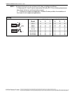
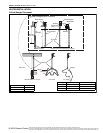
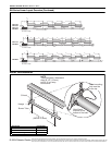
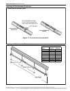
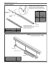
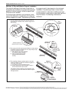
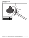
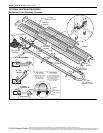
Coupling a nd Tube Asse mbly (Continued)
Coupling a nd Tube Asse mbly (Continued)
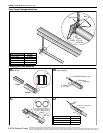
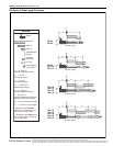
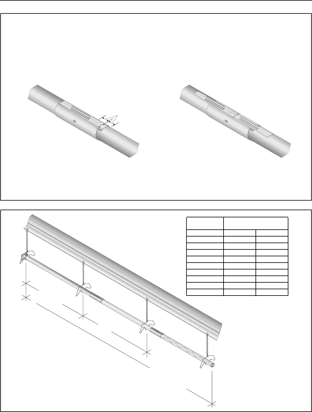
Incorrect Slide Bar
position
Correct Slide Bar
dimensions
± 2" (5 cm)
Drive Slide Bar until tight.
End of Slide Bar should be
within tolerance listed below.
• Repeat A - D until all tubes are assembled.
Tighten slide bar as shown below
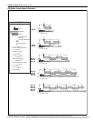
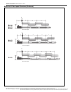
10' ± 1'
(305 cm ± 25 cm)
Total Overall
Tube Length
7' 6" ± 1'
(229 cm ± 25 cm)
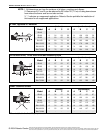
Model
Tube Length
Minimum Maximum
BH-40 10’ (3 m) 10’ (3 m)
BH-60 20’ (6 m) 20’ (6 m)
BH-80 20’ (6 m) 30’ (9 m)
BH-100 30’ (9 m) 40’ (12 m)
BH-115 30’ (9 m) 50’ (15 m)
BH-125 40’ (12 m) 50’ (15 m)
BH-140 40’ (12 m) 60’ (18 m)
BH-150 50’ (15 m) 60’ (18 m)
BH-175 50’ (15 m) 70’ (21 m)
BH-200 60’ (18 m) 80’ (24 m)