


© 2004
All rights reserved. No part of this work covered by the copyrights herein may be reproduced
or copied in any form or by any means - graphic, electronic, or mechanical, including
photocopying, recording, taping or information storage and retrieval systems - without the
written permission of Roberts-Gordon.
TABLE OF CONTENTS
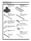
STANDARD PARTS LIST............................................. 1
Contents of BH-Series Burner Carton ..................... 1
Contents of Core and Extension Packages............. 1
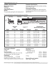
GENERAL SPECIFICATIONS ......................................2
Material Specification .............................................. 2
Reflectors ................................................................ 2
Heater Specifications...............................................2
Ignition .....................................................................2
Suspension Specifications....................................... 2
Controls Specifications ............................................ 2
Gas Pressure at Manifold........................................ 2
Pipe Connection...................................................... 2
Dimensions.............................................................. 2
Gas Inlet Pressure...................................................2
Electrical Rating (all models)................................... 2
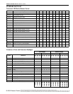
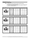
CLEARANCES TO COMBUSTIBLES .......................... 3
Standard Reflector...................................................3
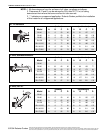
One Side Reflector .................................................. 3
Two Side Reflectors ................................................ 3
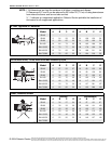
45° Tilt Reflector...................................................... 4
U-Tube, Standard Reflector..................................... 4
U-Tube, Full 45° ...................................................... 4
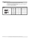
U-Tube, Opposite 45° Reflector .............................. 5
2-Foot Deco Grille, 1-Foot Deco Grille
and Protective Grille ................................................ 5
Lower Clearance Shield ..........................................5
Venting .................................................................... 6
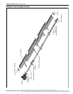
BH-SERIES ASSEMBLY OVERVIEW.......................... 7
Major Component Descriptions ............................... 7
BH-Series Linear Assembly Overview ....................8
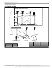
HEATER INSTALLATION............................................. 9
Critical Hanger Placement....................................... 9
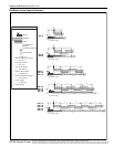
BH-Series Linear Layout Overview ........................10
BH-Series Linear Layout Overview (Continued)......11
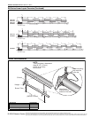
Burner Tube Installation ..........................................11
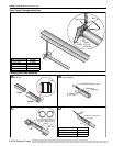
Tube Clamp Package Installation............................ 12
Coupling and Tube Assembly.................................. 12
Coupling and Tube Assembly (Continued).............. 13
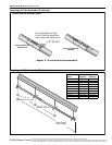
Turbulator Installation.............................................. 14
Reflector Installation ................................................ 14
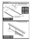
Reflector, U-Clip and Reflector Support
Installation ............................................................... 15
Burner Installation.................................................... 16
OPTIONAL HEATER ACCESSORIES.......................... 17
BH-Series U-Tube Assembly Overview .................. 17
BH-Series U-Tube Layout Overviews ..................... 18
BH-Series U- Tube Layout Overview s (Continued) .. 19
Elbow Package Configuration .................................20
Elbow Installation..................................................... 20
Elbow Installation (continued) ..................................20
Reflector Joint Installation........................................20
Reflector Joint Detail................................................21
REFLECTOR SIDE EXTENSION ..................................22
Bracket Installation...................................................22
Side Reflector Installation........................................22
LOWER CLEARANCE SHIELD INSTALLATION.........23
Shield Support Strap Assembly...............................23
TWO-FOOT DECORATIVE GRILLE INSTALLATION..23
Grille Installation......................................................23
Frame Shield Installation.........................................24
Reflector Side Extension Installation ......................24
ONE-FOOT DECORATIVE GRILLE INSTALLATION..25
One-Foot Decorative Grille Bracket.........................25
Decorative Grille......................................................25
Joint Piece and Reinforcement................................25
End Piece and Reflector End Cap...........................26
90° Elbow.................................................................26
PROTECTIVE GRILLE INSTALLATION.......................27
Silicone Cap Installation...........................................27
Grille End Cap Installation .......................................27
Grille Installation......................................................27
VENTING........................................................................28
Horizontal Ventilation 4" (10 cm) Pipe .....................28
Vertical Ventilation 4" (10 cm) Pipe..........................28
Common Sidewall Venting.......................................29
Common Vertical Venting .......................................30
OUTSIDE COMBUSTION AIR SUPPLY.......................31
Vertical Outside Air Supply for
Single Heater Installation.........................................31
Horizontal Outside Air Supply for
Single Heater Installation.........................................31
Vertical Outside Air Supply for
Double Heater Installation........................................32
Horizontal Outside Air Supply for
Double Heater Installation........................................32
GAS PIPING...................................................................33
Gas Connection with Stainless Steel
Flex Connector.........................................................33
WIRING..........................................................................34
Line Voltage Thermostat Wiring...............................34
Low Voltage Thermostat Wiring...............................35
BH-Series Internal Wiring ........................................36
BH-Series Ladder Diagram......................................36
Electrical Connection to the Burner .........................37
INTERNAL BURNER DIAGRAM...................................38
THE ROBERTS GORDON
®
GORDONRAY
®
BH
LIMITED WARRANTY...................................................39
Printed in U.S.A.