


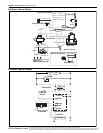

ROBERTS GORDON
®
BH-SER I ES SUBMITTAL SHEET
© 2004 Roberts-Gordon
BEFORE IN STALLATION AND OPERATION OF HEATING EQUIPMENT, READ AND U NDERSTAND THE INSTALLATION, OPERATION AND SERVICE MANUAL.
APPLICATION S, ENGINEERING AND DETAI LED GUID ANCE ON SYSTEMS DE SIGN, INSTALLATION AND PRODUCT PERFORMANCE IS AVAI LABLE UPON REQUEST. ROBERTS GORDON
®
PRODUCTS ARE TO BE
INSTALLED ONLY IN ACCORDANCE WI TH L OCAL LAWS, CODES AND REGULATIONS, AND ONLY BY A CONTRACTOR QUALIFIED I N THE INST ALLAT ION AND SERVICE OF GAS-FIRED HEATING EQUIPMENT.
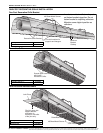
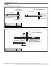
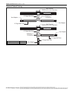
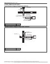
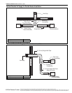
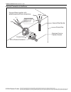
GAS PIPING
Gas Connection with Stainless Steel Flex Connector
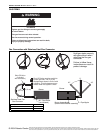
WARNING
Fire Hazard
Tighten gas line fittings to connect gas supply
as shown below.
Flex gas line can crack when twisted.
Gas line moves during normal operation.
Failure to follow these instructions can result in death,
injury or property damage.
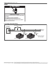
45°
Burner Assembly
(shown without blower assembly)
Pipe Nipple
Burner
45°
0°
Shut-Off Valve must be parallel to
burner gas inlet. The 2" (5 cm)
displacement shown is for the cold
condition. This displacement may
reduce when the system is fired.
Shut-Off Valve
(included
with connector)
Stainless Steel Flex
Gas Connector
90 ° Pipe Elbow
(not included)
Burner
2" (5 cm)
12"
(30 cm)
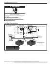
Hold gas nipple securely
with pipe wrench when
attaching the flex gas
connector.
Failure to follow these
instructions can result in
product damage.
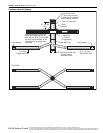
Description Part Number
1/2” Flex Gas Line 91412200
3/4” Flex Gas Line 91412203