


ROBERTS GORDON
®
BH-SER I ES SUBMITTAL SHEET
© 2004 Roberts-Gordon
BEFORE IN STALLATION AND OPERATION OF HEATING EQUIPMENT, READ AND U NDERSTAND THE INSTALLATION, OPERATION AND SERVICE MANUAL.
APPLICATION S, ENGINEERING AND DETAI LED GUID ANCE ON SYSTEMS DE SIGN, INSTALLATION AND PRODUCT PERFORMANCE IS AVAI LABLE UPON REQUEST. ROBERTS GORDON
®
PRODUCTS ARE TO BE
INSTALLED ONLY IN ACCORDANCE WI TH L OCAL LAWS, CODES AND REGULATIONS, AND ONLY BY A CONTRACTOR QUALIFIED I N THE INST ALLAT ION AND SERVICE OF GAS-FIRED HEATING EQUIPMENT.
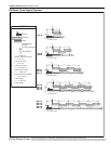
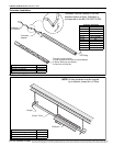
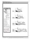
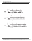
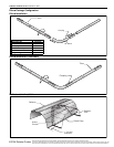
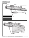
BH-Series U-Tube Layout Overviews
LEGEND
a = 14" (36 cm)
reflector width (not shown)
b = 2" (5 cm)
end cap to burner
c = 2" (5 cm)
end cap to hanger
d = 7'6" (229 cm)
distance first hanger
e = 10' (305 cm)
distance between hangers
f = 5' (153 cm)
distance between last full tube
hanger and half tube hanger
g = 12.5" (32 cm) burner length
h = 11" (28 cm) burner height
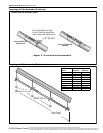
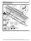
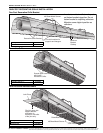
* Require the last reflector
before the U-Tube to be cut in
half for use on both sides.
** Require the last tube before
the U-Tube to be cut in half for
use on both sides.
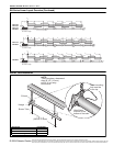
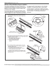
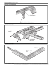
U-Tube
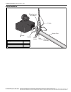
Burner
Reflector
Tube 10'
Tube/Reflector
Hanger
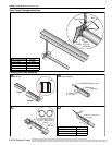
Coupling
Assembly
Tube 5' **
c
b
de
g
h
40' Tube Length
c
b
d
f
g
h
30' Tube Length**
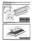
20' Tube Length*
BH-80
BH-100
BH-115
BH-60
BH-80
BH-100
BH-115
BH-125
BH-140
g
c
b
h
e
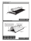
BH-115
BH-125
BH-140
BH-150
BH-175
c
b
de
f
g
h
50' Tube Length* **
Vent Adapter
(not shown)