


Installation & Servicing Instructions Rinnai E-Series
47
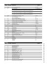
Parameter Mode
PARA FACTORY
DESCRIPTION
RANGE
. . . .
1 186°F maximum supply temperature CH 68 - 186°F
2* 00 type of CH installation:
01 DO NOT USE
radiators with large surface areas or underfloor heating as additional heating:
T max. supply 158°F K factor heating curve 1.8; gradient 10°F/min; gear differential 10°F
02
under floor heating with radiators as additional heating:
T max. supply 140°F; K factor heating curve 1.5; gradient 8°F/min; gear differential 8°F
03
full under floor heating:
T max. supply 122°F; K factor heating curve 1.0; gradient 6°F/min; gear differential 6°F
04
3 max. maximum power CH in kW (.. x3415 = .. BTU/hr) min-ma
x
4* 00 control principal with on / off thermostat:
100 % on / off thermostat 00
100 % on / off weather dependan
t
01
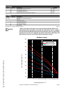
5* 2.3 heating curve K-factor (see also heating curve graph
)
0.2 - 3.5
6* 1.4 heating curve exponent (see also heating curve graph) 1.1 - 1.4
7* 14°F heating curve climate zone (see also heating curve graph) -4 - 32°F
10* 0°F fine adjustment heating curve day temperature -8 to 10°F
11* 0°F fine adjustment heating curve night temperature -8 to 10°F
14 10°F/min. gradient speed °F/min. 0 - 28°F/min.
15* 00 Booster after night decrease*:
no 00
yes 01
23 26°F Frost Temperature -4 to 50°F
27 32°F Minimum T-set CH 0 - 158°F
31 132°F DHW temperature 68 - 176°F
36 20 Type of three way valve DHW fascility
VC 2010 / VC 8010 x0
Flowswitch 2x
43 max. Maximum power DHW in kW (.. x3415 = .. BTU/hr) min-max
49 100% Maximum pump capacity heating 100 %
73 0 Altitude and venting CFT. See chapter 6.7.7 0 - 100
89 00 Address
No function -01
Bus thermostat 00
90 01 Display reading
°C and Ba
r
00
°F and PSI 01
. . . .
Info Mode
INFO
FACTORY
DESCRIPTION
RANGE
. . . .
1 °F supply water temperature T1
4 °F return water temperature T2
5 °F DHW temperature T3
7 °F outdoor temperature T
4
8 °F flue gas temperature T5 (optional sensor
)
16 % actual power in %
17 kW actual power in kW (.. x3415 = .. BTU/hr)
18 kW actual load in kW (.. x3415 = .. BTU/hr)
20 indication bus communication
21 GJ consumption total in GJ (.. x 33 = .. m3)
22 GJ consumption CH in GJ (.. x 33 = .. m3)
23 GJ consumption DHW in GJ (.. x 33 = .. m3)
24 h total number of burner run hour
s
25 h number of burner run hours CH
26 h number of burner run hours DH
W
32 h total number of hours counter
37 h total number of run hours pump CH and DHW
46 h within how many hours is service required
. . .