


Installation & Servicing Instructions Rinnai E-Series
37
7 Electrical connections
The electrical connections to the boiler must be made in accordance with all applicable
local codes and the latest revision of the National Electrical Code, ANSI/NFPA-70.
Installations should also conform with CSA C22.1 Canadian Electrical Code Part 1
if installed in Canada.
Devices such as, outdoor sensor, room thermostat or temperature control, temperature
sensor or thermostat and an external pump are all connected to the internal connection
terminal. The connection terminal is situated behind the Control Tower.
Connecting incoming power
Install a 120V main switch next to the boiler as service main switch of the boiler.
Lead the cable through the back part of the boiler using a strain relief and lead the
cable through the cable supports to the Control Tower.
Connect a power supply cable to the cable harness terminal strip that connects to
both the power switch on the front of the Control Tower and the terminal strip with
positions 1, 2, and 3 on the inside of the Control Tower.
The boiler must be electrically grounded in accordance with local codes, or
in absence of local codes, with the National Electrical Code, ANSI/INFPA 70
and/or the CSA C22.1, Electrical Code.
RISK OF ELECTRIC SHOCK.
Once the main power supply is on then there is 120V on terminals 1 to 12 if the main
switch next to the boiler is switched on.
- No changes may be made to the wiring of the boiler;
- All connections should be designed in accordance with the applicable
regulations;
The Rinnai room thermostat and controls must be connected to their allocated
connections. All other types or makes of room thermostats or controls which
are used must have a Volt free contact.
When using an on/off thermostat or control, it is possible that an anticipating resistance
must be calibrated in order to prevent too high temperature uctuations. As a standard
rule this means mercury thermostats. This resistance wire is present in the Control
Tower and must be connected to clamps 23 and 27. The anticipating resistance in
the room thermostat has to be set at 0.11 A.
For more detailed questions regarding the components which are not supplied, the
distributor should be contacted.
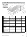
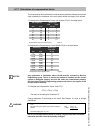
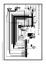
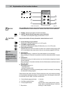
Connection terminal E-Series
Connection terminal gure 19
120 Volts for
external pump
main power
supply
120 Volts for
external control
120 Volts
internal three-way
valve motor
and
DHW sensor
Bus
room thermostat
On/off thermostat or
control (Volt free)
ARV12 outdoor
sensor
External safety
contact
24 Volts
maximum 100 mA
CAUTION
CAUTION
CAUTION
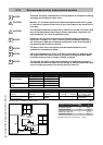
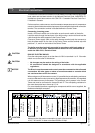
Make sure that the power consumption of each of the terminals
4-5-6, 7-8-9 and10-11 does not exceed 230W or 2 Amp.
!
CAUTION
NOTICE
i
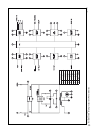
120 V~
120 V~ 120 V~
Power supply External pump
Cylinder connection
8U352200
Outside
sensor
Bus
Controller
24 V~
100 mA
N L
N L
CH
DHW
N
DHW
sensor
three-way valve
Room
therm.
On / Off
External
safety
contact
120 V~
Ext.controller
7
4
5 6 10
11