


Installation & Servicing Instructions Rinnai E-Series
28
6.7.3 Installation of the vent system
Consult local and state codes pertaining to special building code and re department
requirements. Adhere to national code requirements.
Follow the listed maximum length of vent systems, which are boiler output dependent.
The maximum permissible lengths are listed in table 9, chapter 6.7.6.
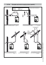
Decide how to install the exhaust and air intake system. You can choose between:
- Concentric system (see page 26)
The concentric connection is provided standard initially.
The boiler concentric connection diameter is 3"/5" (80/125 mm), to which the venting and air
supply system can be tted, with or without elbow pieces. The maximum permissible pipe length
is displayed in table 9, chapter 6.7.6.
- Parallel system (see page 27)
The boiler can be converted to a parallel system with supplied adapters.
It is possible to use a parallel pipe connection of 2x 3". In this case a seperate supplied kit, with
2 vent adapters 3" (ø80mm), cover 5" (ø125mm), vent exhaust pipe and gaskets should be
tted instead of the concentric vent adapter on top of the boiler. See gure 12 for installation.
The maximum permissible pipe length is set out in table 9, chapter 6.7.6.
- Room Air System (outdoor combustion air)
The boiler can use room air for combustion. If this option is selected the boiler must rst be
converted to the Parallel system. A single exhaust pipe can then be tted. It is required to use
a room air lter when using indoor air for combustion. The maximum permissible pipe length
is set out in table 9, chapter 6.7.6.
We advise to install a vent system out of the venting system program supplied by
Rinnai (See chapter 19 Parts list Vent system). For further information about the
available components of the venting and air supply system we recommend you
consult Rinnai and the Installation instructions and parts list documentation.
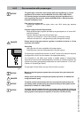
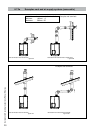
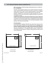
A B C D
1
2
3
4
5
8
6
7
9
10
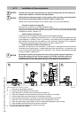
A. 1. Push the 2 clips slightly outwards
B. 2. Pull the concentric adaptor out of the boiler
3. Press the cover in the connection at the back from inside out
C. 4. Push the 3" adapter into the connection at the back of the boiler (= air intake)
5. Pull the rubber seal around the bottom of the exhaust connector
6. Push the exhaust connector in the boiler, in the boiler exhaust pipe until 'CLICK'
7. Push the 5" cover over the exhaust connector in the 5" opening until 'CLICK'
8. Push the rubber plug in open position in the O
2
measuring opening and close the stop.
9. Push the gasket around the top of the exhaust connector
10. Push the 3" exhaust adaptor in the exhaust connector.
D. Connect the parallel vent system.
boiler conversion from concentric to parallel gure 12
NOTICE
i
NOTICE
i
NOTICE
i