


Regency
®
F33-3 Freestanding Gas Stove 9
INSTALLATION
SYSTEM DATA
NG LPG
Injector size # 36 # 52
Input Rating 33 mj 33 mj
Manifold Pressure 0.8 kPa 2.38 kPa
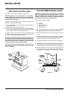
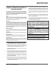
GAS PIPE PRESSURE TESTING
The appliance must be isolated from the gas supply piping system
by closing its individual manual shut-off valve during any pressure
testing of the gas supply piping system at test pressures equal to or
less than 3.45 kPa. Disconnect piping from valve at pressures over
3.45 kPa.
The manifold pressure is controlled by a regulator built into the gas
control, and should be checked at the pressure test point.
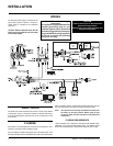
Note: To properly check gas pressure, both inlet and manifold
pressures should be checked using the valve pressure
ports on the valve.
1) Make sure the valve is in the "OFF" position.
2) Loosen the "IN" and/or "OUT" pressure tap(s), turning counter-
clockwise with a 1/8" wide fl at screwdriver.
3) Attach manometer to "IN" and/or "OUT" pressure tap(s) using a
5/16" ID hose.
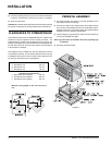
GAS CONNECTION
The gas connection is a 1/2 inch BSP Male thread. The gas line can
be rigid copper pipe. Pipe size to ensure correct operating pressure.
For minimum and maximum supply pressure see the System Data
table below.
Note: During any pressure testing of the gas supply piping
system that exceeds test pressures of 3.45 kPa, this ap-
pliance and its individual shut-off valve must be discon-
nected from the piping system. If test pressures equal to
or less than 3.45 kPa are used then this appliance can be
isolated from the piping system by closing its individual
manual shut-off valve, if fi tted, during the testing.
INSTALLATION IS TO BE CARRIED OUT
ONLY BY AN AUTHORISED PERSON
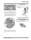
4) Light the pilot and turn the valve to "ON" position.
5) The pressure check should be carried out with the unit burning
and the setting should be within the limits specifi ed on the safety
label.
6) When fi nished reading manometer, turn off the gas valve, discon-
nect the hose and tighten the screw (clockwise) with a 1/8" fl at
screwdriver. Screw should be snug, but do not over tighten.
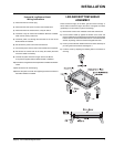
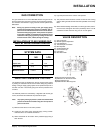
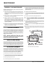
1) Gas on/off knob
2) Manual high/low adjustment
3) Pilot Adjustment
4) Thermocouple Connection
5) Main Operator
6) Outlet Pressure Tap
7) Inlet Pressure Tap
8) Pilot Outlet
9) Main Gas Outlet
VALVE DESCRIPTION
10) Flange Securing Screw Holes
11) Alternative TC Connection Point
12) Thermoelectric Unit
13) Additional Valve Mounting Hole