


Regency
®
F33-3 Freestanding Gas Stove 17
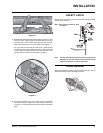
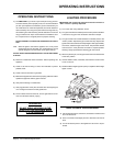
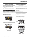
REMOVING VALVE ASSEMBLY
1) Shut off gas supply.
2) If optional fan is installed, disconnect power source to stove.
3) Remove access panel.
a) Front panel on pedestal model. See diagram 1.
b) Panel from bottom of leg shield. See diagram 2.
Note: Access panel only has to be loosened to be taken out.
Diagram 1
Diagram 2
AERATION ADJUSTMENT
The burner aeration is factory set. Adjustment may be needed due to the
local gas supply or altitude. As a general rule if the fl ame is too yellow
open up the air shutter, if it is too blue close the air shutter.
NG 11 mm
LPG wide open
Note: This adjustment only to be made by an authorised
person.
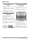
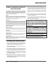
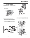
PILOT ADJUSTMENT
Periodically check the pilot fl ames. Correct fl ame pattern has three
strong blue fl ames: 1 fl owing around the thermopile, 1 around the
thermocouple and 1 fl owing across the burner (it does not have
to be touching the burner).
Note: If you have an incorrect fl ame pattern, contact your
Regency
®
dealer for further instructions.
MAINTENANCE
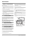
Incorrect fl ame pattern will have small, probably yellow fl ames,
not coming into proper contact with the rear burner or thermopile
or thermocouple.
Top View of pilot fl ame
Top View of pilot fl ame
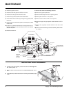
THERMOPILE/THERMOCOUPLE
REPLACEMENT
1) Loosen the thermocouple or thermopile with a 9mm spanner at
bracket.
2) Disconnect thermocouple by loosening nut from the valve with
a 9mm spanner. Disconnect thermopile by loosening 2 screws
marked TP on the valve.
3) Drop the thermocouple or thermopile down from the bracket and
pull it out of the unit.
4) Reinstall the new ones in reverse order.