


6 Regency
®
F33-3 Freestanding Gas Stove
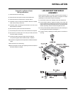
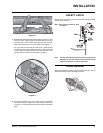
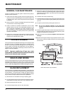
PEDESTAL ASSEMBLY
1) For easier assembly, tip the stove on its back (preferably onto a
soft surface to prevent scratching).
2) Unscrew the 4 bolts in the underside of the stove. Align the holes
in the corners of the pedestal top with the corresponding holes in
the base of the stove. Use washers which are supplied with the
pedestal as shown in diagram. Reinstall bolts.
3) Push the Regency
®
logo into the two holes in the front bottom left
corner of the pedestal cover plate.
Note: Any paint touch up should be done prior to placing logo
on pedestal.
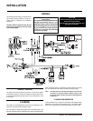
4) See wiring instructions below.
Diagram 1
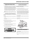
INSTALLATION
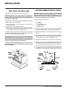
2) If required, adjusting the primary air to ensure that the fl ame does
not carbon. First allow the unit to burn for 15-20 min. to stabilize.
3) Check for proper draft.
CAUTION: Any alteration to the product that causes sooting or carboning
that results in damage is not the responsibility of the manufacturer.
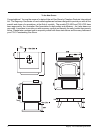
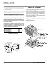
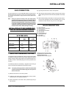
CLEARANCES TO COMBUSTIBLES
The clearances listed below are MINIMUM distances. Measure the
clearance to both the appliance and the chimney connector. The
farthest distance is correct if the two clearances do not coincide. For
example, if the appliance is set as indicated in one of the diagrams but
the back wall is too close, move the stove until the correct clearance
to the connector is obtained.
This appliance may be installed only with the clearances as shown
in the situations pictured. Do not combine clearances from one type
of installation with another in order to achieve closer clearances. Use
the minimum clearances shown in the diagrams.
F33-3 Clearance to Combustibles
A Side Wall to Unit 250 mm
B Back Wall to Unit 150 mm
E Side Wall to Unit 38 mm
F33-3 Reference Dimensions
C Back Wall to Flue Centerline 292 mm
D Side Wall to Flue Centerline 559 mm
F Side Wall to Flue Centerline 330 mm
Minimum ceiling height is 914 mm from top of
unit.