


18 Regency
®
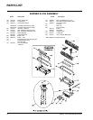
F33-3 Freestanding Gas Stove
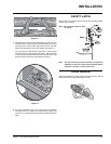
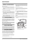
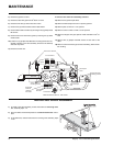
VIEW FROM BOTTOM OF THE STOVE
Front of Stove
Piezo
Ignitor
Hi/Lo
On/Off
Front Cover Screws
Thermopile
wires
Orifice assembly
mounting screws
Orifice
Thermocouple
wire
Thermocouple
nut
Gas Inlet
Gas Outlet
Valve
mounting screws
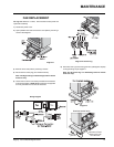
Thermodisc
Bracket
Thermodisc
x
1
T-O-D
3
SA
9426
L200-40F
9426
L200-40F
313717
T-O-D 60711
313717
T-O-D
60711
x
1
T-O-D
3
SA
9426
L200-40F
9426
L200-40F
313717
T-O-D 60711
313717
T-O-D
60711
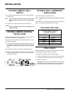
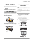
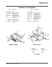
WARNING
240 Volts
Placement
of Decal
“Warning
240 Volts”
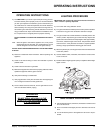
MAINTENANCE
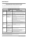
4) Disconnect gas line to stove.
5) Disconnect 3/8" NPT pipe from 90
o
elbow on valve.
6) Disconnect the two (2) switch wires from valve.
7) Remove two (2) orifi ce bracket screws inside fi rebox.
8) Remove thermodisc to bracket by removing three (3) phillips head
M5 screws.
9) Remove front cover with Piezo Igniter by removing two (2) sheet
metal screws.
10) Loosen four (4) phillips head M5 valve mounting screws from un-
derside of fi rebox. Push valve assembly forward on the teardrop
slots and drop down.
11) Disconnect Piezo wire.
To remove valve from valve assembly, continue.
12) Remove two (2) thermopile wires.
13) Remove thermocouple with a 9 mm (metric) spanner.
14) Remove pilot nut with an 11 mm spanner.
15) Remove valve to orifi ce nut with a 13/16" spanner.
16) Remove inlet pipe with pipe spanner. Note orientation of 90
o
el-
bow.
17) Remove two (2) phillips head M5 screws on each side of the
valve.
18) Remove valve and remove gas out 90
o
brass fi tting. Note orienta-
tion of fi tting.
INSTALLING VALVE ASSEMBLY
1) To install a new valve assembly, reverse instructions for removing valve.
See assembly steps 1-11.
2) Check for leaks and manifold pressure. See Gas Pressure Test instruc-
tions.
3) To reinstall valve, reverse instructions for removing valve assembly, steps
12-18.