


Regency
®
CLASSIC C33-3 Freestanding Gas Stove 9
VENTING
This heater is a vented appliance and must be
connected to a chimney/fl ue in accordance with
installation codes.
Note: The rear cover plate is only attached
when outside air is being used. Do
not install it when using room air for
combustion.
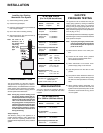
For your safety this heater is equipped with a
vent safety switch. This thermally actuated switch
is located within the draft hood and will detect
either a blocked chimney or backdraft condition
where the chimney fl ow has reversed and will
react by shutting off the gas supply.
Note: The spill switch is manually resettable
and comes from the factory in the
open position. Before trying to start
up the unit, make sure the red button
on the spill switch is pushed in.
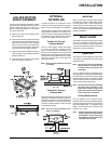
Venting Requirements
Four inch diameter vent is required. B-Vent,
Class A or Masonry with a liner are all acceptable.
Follow all venting manufacturer’s requirements
and local building codes. For altitudes above
2000 ft. we recommend that a minimum fl ue
height of 12 ft. is used.
Note: Proper sizing of gas vents is critical
to proper operation of all gas stoves
and fi replaces. Ensure that proper
sizing tables or vent manufacturers
instructions are followed.
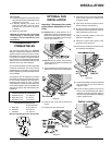
OPTIONAL
OUTSIDE AIR
If needed, outside air for combustion can be
brought in either through the bottom of the ped-
estal or through the rear plate of the pedestal.
The pedestal cover plate must be installed when
using outside combustion air. Loosen the 4
screws on the rear of the pedestal and slide the
cover plate over them. Slide the plate to the left
to center it and tighten down the 4 screws.
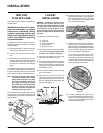
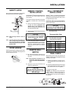
Outside Air Through
Pedestal Bottom
Once you have properly marked the position
of your unit as outlined in "General Informa-
tion" and "Clearances to Combustibles", cut a
minimum 3 inch diameter hole though the fl oor
directly under your pedestal base to the outside.
Pipe fresh air into the pedestal area by using a
minimum 3" duct pipe with a mesh grill at the
outside termination.
Note: Blanking plate combustion air hole is
4" diameter.
IMPORTANT
Read all instructions carefully before starting
the installation. Failure to follow these instruc-
tions may create a fi re or other safety hazard,
and will void the warranty. Be sure to check the
venting and clearance to combustible require-
ments. Consult your local building codes before
beginning installation.
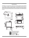
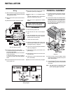
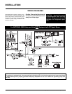
Rear View
Side View
DRAFT HOOD
The heater has a draft hood built into its back.
It must not be altered or obstructed, and the
unit must be installed so that the draft hood is
in the same atmospheric pressure zone as the
combustion air inlet to the burner.
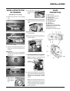
LEG AND BOTTOM
SHIELD ASSEMBLY
These instructions apply to the steel leg, painted
cast leg and the gold plated cast leg. It will be
easier to attach the legs to the stove if it is
tipped on its back (preferably on a soft surface
to prevent scratching).
1) Remove the 4 bolts in the underside of the
base and discard.
2) Put the bottom shield up against the bottom
of the stove and loosely install the four sup-
plied bolts and washers into the threaded
holes in the four corners of the bottom the
unit. Once the bolts are started, slip the leg
under the washer and tighten the bolts.
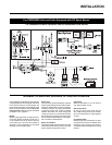
3) Hook up wires to Burner ON/OFF switch and
valve assembly as per pedestal assembly
diagram (diagram 1).
4) Level the stove by adjusting the levelling
bolts in the bottom of each leg.
INSTALLATION
Outside Air Through
Pedestal Rear
Remove the blanking plate from the rear of the
pedestal cover plate and bend the two tabs out
90 degrees. Pipe fresh air into the pedestal area
by using a minimum 3" duct pipe with a mesh
grill at the outside termination. Attach the pipe
to the tabs with screws.
Note: The hole in the rear pedestal cover
plate is 4" diameter.