


Regency
®
CLASSIC C33-3 Freestanding Gas Stove 11
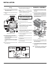
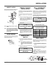
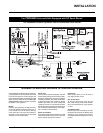
VALVE
DESCRIPTION
1) Gas on/off knob
2) Manual high/low adjustment
3) Pilot Adjustment
4) Thermocouple Connection
5) Main Operator
6) Outlet Pressure Tap
7) Inlet Pressure Tap
8) Pilot Outlet
9) Main Gas Outlet
10) Flange Securing Screw Holes
11) Alternative TC Connection Point
12) Thermoelectric Unit
13) Additional Valve Mounting Hole
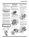
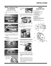
INSTALLATION OF THE
DC SPARKER
1) Attach the ground wire to the grounding
stub.
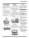
After
Before
4) Loop the wires
through the heat
shield.
5) Install the plastic bushing over the outside of
the hole to protect the wires from the sharp
edges.
6a) Attach the ground wire to the DC spark
mounting bracket.
6b) Next, attach the DC sparker generator wires
to the DC sparker.
ground wire
DC spark generating wires
Piezo ignition wires
2) Loop the 2 DC Spark generating wires as
well as the ground wire through the hole
provided.
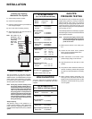
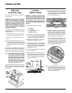
With Bottom Shield:
With Pedestal:
Select the hole to be used (depending
on which side you prefer to install the DC
Sparker box).
8) Attach the heat shield to the DC Sparker,
then mount onto either the Pedestal or the
Bottom Shield, using the velcro already
attached to the DC Sparker mounting
bracket.
Note: We recommend attaching the DC
sparker box to the bottom rear of the unit
(away from the heat source). Ensure this
a convenient location, easily accessible for
battery replacement.
3) Attach the Piezo
Ignition wire to
the DC Sparker
box.
INSTALLATION
7) Install the supplied battery into the DC Sparker
Box by opening the battery compartment.
NOTE: The battery in the DC Sparker Box
will need to be replaced annually.
Battery
Compartment
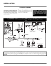
(APPLIES ONLY TO LP UNITS)