


Regency
®
CLASSIC C33-3 Freestanding Gas Stove 13
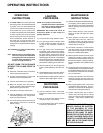
FINAL CHECK
Before leaving this unit with the customer, the
installer must ensure that the appliance is fi ring
correctly. This includes:
1) Clocking the appliance to ensure the cor-
rect fi ring rate (rate noted on label) after 15
minutes.
2) If required, adjusting the primary air to ensure
that the fl ame does not carbon. First allow
the unit to burn for 15 min. to stabilize.
3) Check for proper draft.
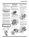
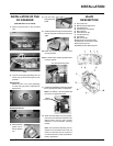
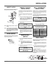
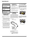
SAFETY LATCH
Secure door in the closed position using the door
securing bracket and the screw provided.
DOOR HANDLE
Attach spring handle by rotating counter clock-
wise onto rod. Ensure that the spring fi ts into
the entire length of the rod.
Note: Door securing bracket is there for
safety.
Note: The door must be kept closed at all
times, except during maintenance.
The unit must never be operated
without the glass in the door, or with
the door open.
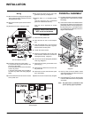
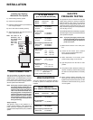
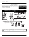
REMOTE CONTROL
INSTALLATION
Use the Regency
®
Remote Control Kit approved
for this unit. Use of other systems may void
your warranty.
The remote control kit comes with a hand held
transmitter, a receiver and a wall mounting
plate.
1) Choose a convenient location on the wall
to install the receiver (protection from
extreme heat is very important). Run
wiresfrom the fi replace to that location. Use
the Thermostat Wire Table.
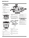
2) Connect the two wires to the gas valve. See
diagram below.
CAUTION
Do not wire the millivolt remote
control wires to the 120V AC
wires.
3) Install 3 AAA alkaline batteries in transmitter
and 4 AA alkaline batteries in the receiver.
Install the receiver and its cover in the wall.
Switch the remote receiver to "remote"
mode. The remote control is now ready for
operation.
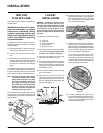
REMOTE WALL
SWITCH
1) Run the wire through the opening in the
rear of the unit. Be careful not to damage
any wires.
Note: We recommend a maximum of 15'
of wire but if you wish to go with a
longer run use the Thermostat Wire
Table.
2) Connect the wire to the wall switch and
install into receptacle box.
CAUTION
Do not wire the millivolt wall
switch for gas appliance to the
120V AC wires
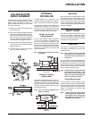
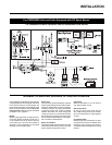
WALL THERMOSTAT
INSTALLATION
Regency
®
offers an optional programmable
thermostat but any 250-750 millivolt rated non-
anticipator type thermostat that is CSA, ULC or
UL approved may be used.
Connect the wires as per the wiring diagram.
Use the Thermostat Wire Table to determine the
maximum wire length.
CAUTION
Do not wire the millivolt wall ther-
mostat wires to the 120V AC wires
Note: Preferable if the thermostat is installed
on an interior wall.
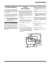
Thermostat Wire Table
CAUTION: Any alteration to the product that
causes sooting or carboning that results in
damage to the unit is not the responsibility of
the manufacturer and will not be covered by
the warranty.
14 GA.
16 GA.
18 GA.
20 GA.
22 GA.
50 Ft.
32 Ft.
20 Ft.
12 Ft.
9 Ft.
Recommended Maximum Lead Length
(Two-Wire) When Using Wall
Thermostat (CP-2 System)
Wire Size Max. Length
INSTALLATION