


10
Regency
®
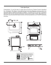
CLASSIC C33-3 Freestanding Gas Stove
HIGH ELEVATION
This unit is approved in Canada for altitude 0
to 4500 ft. (CAN1 2.17-M90) with the orifi ce
supplied.
GAS PIPE
PRESSURE TESTING
The appliance must be isolated from the gas
supply piping system by closing its individual
manual shut-off valve during any pressure
testing of the gas supply piping system at test
pressures equal to or less than 1/2 psig. (3.45
kPa). Disconnect piping from valve at pressures
over 1/2 psig (14" w.c.).
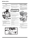
The manifold pressure is controlled by a regulator
built into the gas control, and should be checked
at the pressure test point.
Note: To properly check gas pressure, both
inlet and manifold pressures should
be checked using the valve pressure
ports on the valve.
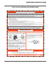
1) Make sure the valve is in the "OFF" posi-
tion.
2) Loosen the "IN" and/or "OUT" pressure
tap(s), turning counterclockwise with a
1/8" wide fl at screwdriver.
3) Attach manometer to "IN" and/or "OUT"
pressure tap(s) using a 5/16" ID hose.
4) Light the pilot and turn the valve to "ON"
position.
5) The pressure check should be carried out
with the unit burning and the setting should
be within the limits specifi ed on the safety
label.
6) When fi nished reading manometer, turn
off the gas valve, disconnect the hose and
tighten the screw (clockwise) with a 1/8" fl at
screwdriver. Screw should be snug, but do
not over tighten.
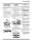
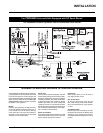
GAS CONNECTION
The gas connection is a 3/8" NPT rigid pipe.
The gas line can be rigid pipe or to make in-
stallation easier, use a listed fl exible connector
and/or copper pipe if allowed by local codes.
For minimum and maximum supply pressure
see the System Data table below.
Note: During any pressure testing of the
gas supply piping system that ex-
ceeds test pressures of 1/2 psig, this
appliance and its individual shut-off
valve must be disconnected from
the piping system. If test pressures
equal to or less than 1/2 psig are used
then this appliance must be isolated
from the piping system by closing
its individual manual shut-off valve
during the testing.
Output capacity:
The effi ciency rating of the appliance is a
product thermal effi ciency rating determined
under continuous operating conditions and
was determined independently of any installed
system.
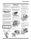
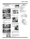
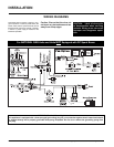
INSTALLATION
Installing into Existing
Woodstove Flue System
1) Clean existing chimney system.
2) Install stove pipe adapter
3) Install any reducers that may be needed to
fi t 6" fl ue pipe adapter.
4) Run 4" fl ex liner into existing chimney.
5) Slip liner through 6" fl ue pipe and hook up
to fl ue collar with screws.
Note: For ease of in-
stallation, use a
slip section when
installing
with a ver-
tical flue
pipe.
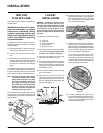
SYSTEM DATA
(For 0 to 2,000 feet altitude)
Orifi ce Sizes:
Burner Natural Gas #36
Burner Propane #52
Max. Input Rating
Natural Gas 33,000 Btu/h
Propane 33,000 Btu/h
Min. Input Rating
Natural Gas 17,000 Btu/h
Propane 17,000 Btu/h
Output Capacity with blower Off
Natural Gas 23,200 Btu/h
Propane 23,100 Btu/h
Output Capacity with blower On
Natural Gas 24,600 Btu/h
Propane 24,420 Btu/h
Supply Pressure
Natural Gas min. 5.0" w.c
max. 8.0" w.c.
Propane min. 12.0" w.c.
max. 13.0" w.c.
Manifold Pressure High
Natural Gas 3.8" +/- 0.2" w.c.
Propane 11" +/- 0.2" w.c.
Manifold Pressure Low
Natural Gas 1.1" +/- 0.2" w.c.
Propane 2.9" +/- 0.2" w.c.
Electrical: 120V, 1.13A, 60 Hz.
Circulation Fan: (optional) 2 speed
75/125 CFM.
Log Set: Ceramic fi ber, 4 per set.
SYSTEM DATA
(For 2,000 to 4,500 feet altitude)
Orifi ce Sizes:
Burner Natural Gas #38
Max. Input Rating
Natural Gas 29,000 Btu/h
Min. Input Rating
Natural Gas 15,300 Btu/h
Output Capacity with blower Off
Natural Gas 20,400 Btu/h
Output Capacity with blower On
Natural Gas 21,600 Btu/h