


20
Regency
®
CLASSIC C33-3 Freestanding Gas Stove
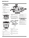
MAINTENANCE
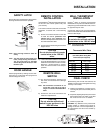
8) If optional fan is installed, remove thermodisc
to bracket by removing three (3) phillips head
M5 screws.
9) Remove front cover with Piezo Igniter by
removing two (2) sheet metal screws.
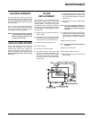
10) Loosen four (4) phillips head M5 valve
mounting screws from underside of fi rebox.
Push valve assembly forward on the teardrop
slots and drop down. Diagram 3.
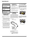
Diagram 1
Diagram 2
4) Disconnect gas line to stove.
5) Disconnect 3/8" NPT pipe from 90
o
elbow
on valve.
6) Disconnect the two (2) switch wires from
valve.
7) Remove two (2) orifi ce bracket screws inside
fi rebox.
Diagram 3
REMOVING
VALVE ASSEMBLY
1) Shut off gas supply.
2) If optional fan is installed, disconnect power
source to stove.
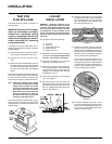
3) Remove access panel.
a) Front panel on pedestal model. See
diagram 1.
b) Panel from bottom of leg shield. See
diagram 2.
Note: Access panel only has to be loos-
ened to be taken out.
11) Disconnect Piezo wire.
To remove valve from valve assembly,
continue.
12) Remove two (2) thermopile wires.
13) Remove thermocouple with a 9 mm (metric)
wrench.
14) Remove pilot nut with an 11 mm wrench.
15) Remove valve to orifi ce nut with a 13/16"
wrench.
16) Remove inlet pipe with pipe wrench. Note
orientation of 90
o
elbow.
17) Remove two (2) phillips head M5 screws
on each side of the valve.
18) Remove valve and remove gas out 90
o
brass
fi tting. Note orientation of fi tting.
INSTALLING
VALVE ASSEMBLY
1) To install a new valve assembly, reverse
instructions for removing valve. See as-
sembly steps 1-11.
2) Check for leaks and manifold pressure. See
Gas Pressure Test instructions.
3) To reinstall valve, reverse instructions for
removing valve assembly, steps 12-18.