


Regency
®
CLASSIC C33-3 Freestanding Gas Stove 7
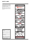
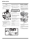
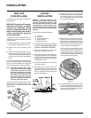
Diagram 4
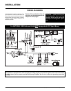
9) Lift the fan assembly in through the pedestal
and up through the cut out as shown in
diagrams 3 and 4.
10) Put the insulation gasket on the back of
the fan. Line up the keyhole slots with the
matching screws and pull back slightly to
lock into place. While holding fan assembly
in place, tighten screws.
Diagram 3
Diagram 2
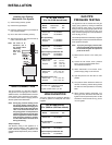
OPTIONAL FAN
INSTALLATION
Important: Disconnect the power
supply before installation or serv-
icing.
For pedestal unit: To install the fan in an in-
stalled stove-access from front through the
pedestal by following the directions below.
If the stove is not installed - access through
rear and follow steps 4 to 17.
Diagram 1
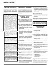
INSTALLATION
CLEARANCES TO
COMBUSTIBLES
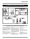
The clearances listed below are MINIMUM
distances. Measure the clearance to both the
appliance and the chimney connector. The far-
thest distance is correct if the two clearances do
not coincide. For example, if the appliance is set
as indicated in one of the diagrams but the back
wall is too close, move the stove until the correct
clearance to the back wall is obtained.
This unit can be installed on a solid combustible
surface like a wood fl oor. This unit can also be
installed directly on carpeting or vinyl when the
bottom pedestal cover plate (provided with the
unit) is installed.
This appliance may be installed only with the
clearances as shown in the situations pictured.
Do not combine clearances from one type of
installation with another in order to achieve
closer clearances. Use the minimum clearances
shown in the diagrams. Alcove installations are
approved, as long as side wall clearances are
maintained.
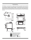
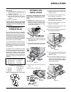
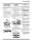
C33-3 Clearances to Combustibles
A Side Wall to Unit 10" / 250 mm
B Back Wall to Unit 6" / 150 mm
E Side Wall to Unit 1.5" / 38 mm
C33-3 Reference Dimensions
to Flue Centerline
C Back Wall 11-1/2"/ 292 mm
D Side Wall 22" / 559 mm
F Side Wall 13" / 330 mm
Minimum ceiling height is 36" / 914 mm from
This includes:
1) Clocking the appliance to ensure the correct
fi ring rate (rate noted on label) after burning
appliance for 15 minutes.
2) If required, adjusting the primary air to
ensure that the fl ame does not carbon.
First allow the unit to burn for 15-20 min.
to stabilize.
3) Check for proper draft.
CAUTION: Any alteration to the product that
causes sooting or carboning that results
in damage is not the responsibility of the
manufacturer.
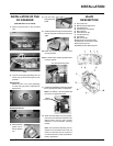
For leg unit: remove 7 screws, remove bottom
access panel and install fan assembly and
follow steps 4 to 17.
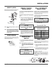
1) Open pedestal door and remove door cover
plate by removing 4 screws. See diagram
1.
2) Remove valve cover plate by removing 2
screws.
3) Remove wire from piezo ignitor.
4) Screw the four 8-32 x 3/4 screws provided
into the nutserts as shown in diagram 3. Do
not tighten screws.
5) Push all the fan wires through the hole on
the fan assembly. See diagram 2
.
6) Put power cord (shown in diagram 3) through
the hole and pull through to front of unit for
easier installation of ground wire.
7) Place fan assembly partially in door cover
plate hole. See diagram 2.
8) Attach the 2 ground wires (green) to the
ground lug as per diagram 2.
Note:Ground lug is located on the bottom of the
fan assembly. See diagram 2.