


Greenfi re Pellet Stove and Insert Technical Manual
16
INSTALLATION
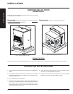
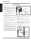
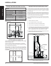
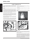
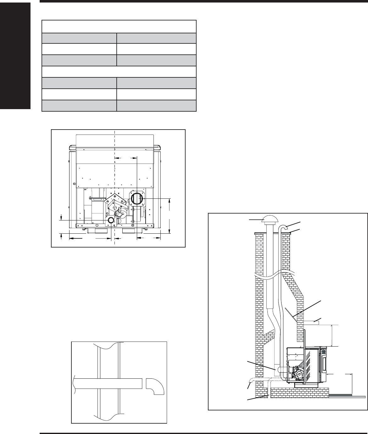
EXHAUST AND FRESH AIR INTAKE LOCATION
EXHAUST:
Base of unit to center of fl ue 9-1/16" (229mm)
Side of unit to center of fl ue 6-1/8" (156mm)
Center of unit to center of fl ue 5-3/4" (146mm)
FRESH AIR INTAKE:
Base of unit to center of intake 3-7/16" (87mm)
Side of unit to center of intake 10-7/8" (277mm)
Center of unit to center of intake 1" (25mm)
INSTALL VENT AT CLEARANCES SPECIFIED BY THE VENTING
MANUFACTURER.
1"
(25mm)
5
3
/4"
(146mm)
3
7
/16"
(87mm)
10
7
/8"
(277mm)
6
1
/8"
(156mm)
9
1
/16"
(229mm)
Figure 26: Insert Inlet and Outlet Location.
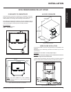
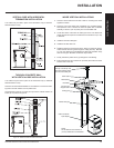
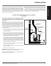
OUTSIDE FRESH AIR CONNECTION
Outside fresh air is mandatory when installing this unit in airtight
homes and mobile homes.
A Fresh-air intake is strongly recommended for all installations.
Failure to install intake air may result in improper combustion as well as
the unit smoking during power failures.
When connecting to an outside fresh air source, do not use plastic or
combustible pipe. A 2” minimum (51 mm) ID (inside diameter) steel,
aluminum or copper pipe should be used. It is recommended, when you
are installing a fresh air system, to keep the number of bends in the pipe
to a minimum.
2" ID
(51 mm)
Optional
Elbow
Outside
Wall
Figure 27: Outside Air Connection.
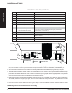
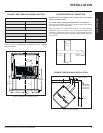
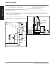
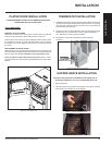
MASONRY FIREPLACE INSERT INSTALLATION
The GFI55 requires a surround faceplate and a pedestal. When installing
this unit, ensure that the pedestal is removed from the inside of the hopper
and installed on the bottom of the unit. Refer to "Installation of Pedestal
and Leveling Legs".
Adjust hopper height - refer to "Installing Hopper Cover and Adjusting Hop-
per Height" and assemble surround panel. See "Installation and Removal
on Control Panel in the Surround Panel" and "Assembly and Installation
of Insert Surround Panels" before starting installation.
A non-combustible hearth pad must cover combustible fl ooring underneath,
as well as 6” (150 mm) in front of the heater and 6” (150 mm) to the side
of the heater
1. Install the hearth pad, if required.
2. Lock the fi replace damper in the open position.
3. Install a positive fl ue connector at the fi replace damper.
4. Connect a tee or 90° degree elbow to the exhaust pipe.
5. This fi replace insert must be installed with a continuous chimney liner
of 3 or 4” diameter extending from the fi replace insert to the top of the
chimney. The liner must conform to type 3 requirements of CAN/ULC
S635. For lengths below 25' use 3" and increase to 4" if longer.
6. (Recommended) Install fresh air intake either through the back of the
fi replace or through the positive fl ue connector.
Floor
Protection
Combustible Floor
Masonry Fireplace
Min. 6"
Rain Cap
Steel Plate or Flashing
Mantel (8" deep)
Fresh-air intake
Clean-out tee
If holes already exist
fresh-air intake can
be taken through the
back of the fireplace
or through the ash
dump.
Damper Removed
or Fastened Open
Min. 8" from
top of stove
Figure 28: Installation of Fireplace Insert.
INSTALLATION