


Greenfi re Pellet Stove and Insert Technical Manual
12
INSTALLATION
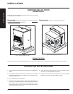
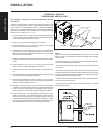
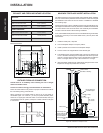
HORIZONTAL EXHAUST
THROUGH WALL INSTALLATION
Vent installation: install vent at clearances specifi ed by the vent
manufacturer.
A chimney connector shall not pass through an attic or roof space, closet
or similar concealed spaces, or a fl oor, or ceiling. Where passage through
a wall or partition of combustible construction is desired, the installation
shall conform to CAN/CSA-B365 Installation Code for Solid-Fuel-Burning
Appliances and Equipment. Only use venting of L or PL type with an inside
diameter of 3 or 4 inches (7.6 or 10.1 cm).
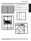
1. Choose a location for your stove that meets the requirements stated
in this manual and allows installation with the least amount of interfer-
ence to house framing, plumbing, wiring, etc.
2. Install a non-combustible hearth pad (where necessary).
3. Place the appliance 15” (37.5 cm) away from the wall. If the stove is
to be set on a hearth pad, set the unit on it.
4. Locate the center of the exhaust pipe on the stove. Extend that line to
the wall. Once you have located the center point on the wall, refer to
pellet vent manufacturer installation instructions for correct hole size
and clearance to combustibles.
5. Install the wall thimble as per the instructions written on the thimble.
Maintain an effective vapour barrier in accordance with local building
codes.
6. Install a length of 3” (76 mm) or 4” (101 mm) vent pipe into the wall
thimble. The pipe should install easily into the thimble.
7. Install the fresh air intake. See "Outside Fresh Air Connection" sec-
tion.
8. Connect the exhaust vent pipe to the exhaust pipe on the stove. Seal
the connection with high temperature silicone.
9. Push the stove straight back, leaving a minimum of 3” (8 cm) clear-
ance from the back of the stove to the wall. Seal the vent pipe to the
thimble with high temperature silicone.
10. The pipe must extend at least 12” (30 cm) away from the building. If
necessary, bring another length of pipe (PL type) to the outside of the
home to connect to the fi rst section. Do not forget to place high tem-
perature silicone around the pipe that passes through the thimble.
11. Install a vertical pipe, or if all requirements for direct venting are met,
install vent termination. The stainless steel cap termination manufac-
tured by the vent manufacturer is recommended. However, when the
vent terminates several feet above ground level and there are no trees,
plants, etc. within several feet, a 45° elbow can be used as termination.
The elbow must be turned down to prevent rain from entering.
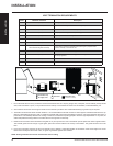
Exhaust Tube
3" (75mm) or 4" (100mm)
"PL" or "L" vent
Wall Thimble
45° Elbow with screen
or Termination Cap
Fresh Air Intake
High Temperature RTV
Silicone Required
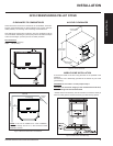
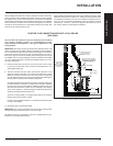
Figure 11: Straight through wall Installation.
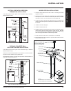
Figure 12: Straight through Wall Installation - Side View.
INSTALLATION
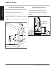
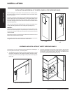
NOTE:
• Some horizontal through wall installations may require a “T” and 3 to 5
feet (91 to 152 cm) of vertical pipe outside the building to help naturally
draft in the unit.
• This may be required if a proper burn cannot be maintained, after the
stove has been tested and the airfl ow set.
• This is due to the back pressure in the exhaust caused by airfl ow around
the structure.
• All sections of pipe must have three (3) screws evenly spaced and all
horizontal and vertical vent sections located within the house must have
a bead of high temperature silicone installed on the male end of the pipe
before installation to create a gas tight seal.
• The termination must be 12 inches (30 cm) from the outside wall and 12
inches (30 cm) above the ground.
• A 45° elbow may be used in place of the termination cap (or stainless
steel termination hood).