


Greenfi re Pellet Stove and Insert Technical Manual 15
INSTALLATION
GFI55 PELLET INSERT
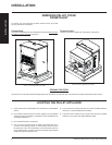
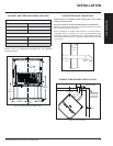
CLEARANCES TO COMBUSTIBLES
The fi replace insert is certifi ed to be installed into a masonry fi replace only
and/or zero clearance wood burning factory built fi replace where allowed
by local codes. This model includes a surround faceplate and a pedestal.
When installing this unit, ensure that the pedestal is removed from the
inside of the hopper and installed on the bottom of the unit.
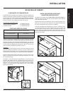
From the body of the heater to the:
Side Wall 8" (203mm) minimum
Facing on Masonry Fireplace: 8" (203mm) minimum
8” (203mm) mantle: 8" (203mm) minimum
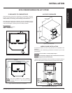
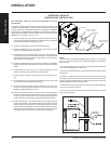
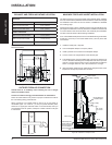
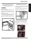
INSTALLATION OF PEDESTAL AND LEVELING LEGS
There are two parts to the GFI55 insert pedestal and they can be found
inside the hopper. Place unit on its back. Two (2) hex head screws are used
on each side of the pedestal (refer to Figure 22). Using a
5
/16” wrench or
socket, secure the pedestal to the bottom of the unit.
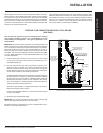
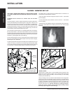
OPTIONAL:
There are two (2) leveling legs and they can be found inside the manual
bag. Each leveling leg consists of a long bolt, a hex nut, a washer, and a
square bolt with clip (see Figure 23). For installation of the leveling legs the
unit should be on its back and a ½” wrench is required for adjustments.
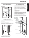
Install the square bolts into the square holes in the back corners of the
bottom. The square bolt should be inserted from inside the unit so that
the clip will be facing up.
Thread hex nut onto the bolt till it is approximately 1” (25 mm) from the
bolt head, slide washer onto bolt. Thread the bolt into the square nut so
length of the bolt shown is the approximately height needed for leveling.
When the unit is up right and the bolts can be adjusted to the exact height
required. To lock the bolts at a height tighten the hex nut and washer
against the square bolt
Leveling Legs
Figure 22: Installing Pedestal.
Figure 23: Square Bolt.
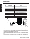
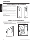
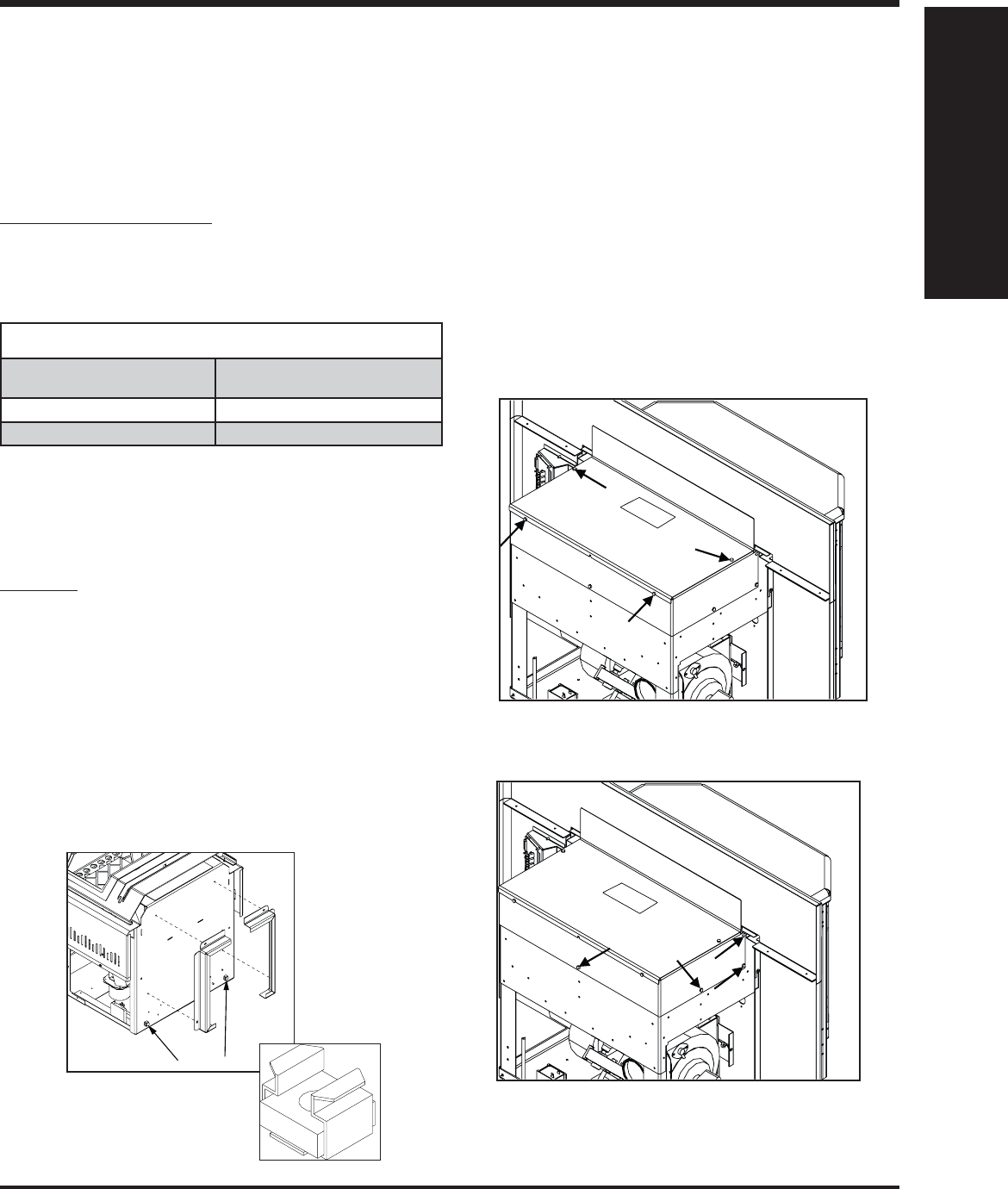
INSTALLING HOPPER COVER AND
ADJUSTING HOPPER HEIGHT
The hopper cover initially comes upside-down on top of the hopper. To
install the hopper cover fl ip the cover over and fasten in place with four
T-20 screws (see Figure 24).
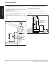
The back height of this unit can be set to one (1) of three (3) heights; 19½”
(495 mm), 21⅛” (537 mm), 22¼” (565 mm). The hopper should be set to
the maximum height that can be used in the installation.
To change the height of the hopper back up or down, remove the seven
(7) T-20 screws, three (3) on each side and one (1) on the back. The
screw placement is shown Figure 25. Move the hopper assembly to the
required setting and replace the screws. When the hopper back is in
place it is recommended that silicone is used to seal the bottom lip of the
hopper back and sides.
Figure 24: Hopper Cover Screw Placement.
Figure 25: Hopper Extension Screw Placement.
INSTALLATION
FIREPLACE SPECIFICATIONS
Your fi replace opening requires the following minimum sizes:
Height 55 lbs hopper (standard)
42 lbs hopper (adjusted)
22.75" (578mm)
19.5" (495mm)
Width 26" (660mm)
Depth 15" (381mm)