


8
FPI U31-2 Gas Fireplace Insert
THIS CONVERSION MUST BE DONE BY A QUALIFIED GAS
FITTER IF IN DOUBT DO NOT DO THIS CONVERSION !!
Conversion Kit from Natural Gas to Propane
Model #402-969 for: U31-NG2 Units
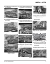
1) Turn the unit off and allow it to cool to room
temperature.
2) Unplug or disconnect power source to
stove.
3) Remove glass front (see manual).
4) Remove logs and brick panels (if in-
stalled).
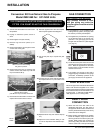
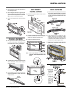
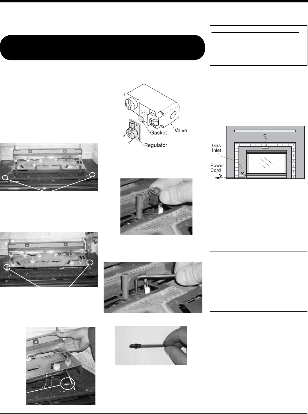
5) Remove the Grate by removing the screws
on each side of the grate.
Remove the 2 screws holding
the grate in position.
Remove the 2 screws,
push Burner Tray to the left, and lift off.
6) Remove the Burner Tray by removing the
screws on each side of the tray. Push the
tray to the left and lift up.
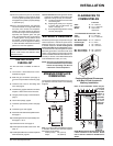
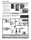
7) Remove burner orifi ce with 1/2" wrench and
replace with the #52 orifi ce in the Kit.
Diagram 1
8) Remove regulator from valve and replace
with Propane regulator. See diagram 1.
Burner
Orifi ce
9) Pull off the pilot cap to expose the pilot
orifi ce.
10) Unscrew the pilot orifi ce with the allen key
and replace with the LP pilot orifi ce in the
kit.
11) Replace Burner Tray and reverse steps 5)
to 1).
12) Adjust the burner aeration setting to 1/8"
to 3/16" as required for the best fl ame pic-
ture.
INSTALLATION
GAS CONNECTION
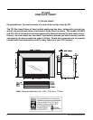
3) Locate the center point where the vent will
pass through the chimney above the appli-
ance. Move the appliance into the exact
location where it is to be installed. Ensure
that the Insert is level.
4) The installer must provide a valve with a
plugged tapping, accessible for test gauge
connection, immediately upstream of the
gas supply connection to the appliance.
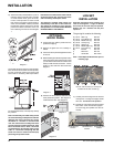
HIGH ELEVATION
This unit is approved in Canada for altitude 0 to
2000 ft. with the orifi ce supplied. For 0' - 4500'
use the optional fi eld conversion kit (Part #400-
970 for Natural Gas units and Part #400-971 for
Propane units). In USA refer to ANSI Z223.1-
1988, Appendix F, for re-sizing orifi ce.
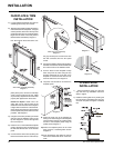
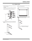
DRAFT HOOD
CONNECTION
1) Attach the vent to the fl ue collar on the
detachable draft hood. The fl ue collar of
the appliance will fi t inside a standard vent
and may be fastened directly to the vent by
sheet metal screw. Diagram 1.
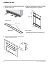
2) Before pushing the appliance into position
inside the fi replace, align the draft hood
with the guides on the insert top and push
forward. While pushing the unit back into
place keep pulling the draft hood forward
until the screw hole in the spill tube aligns
GAS CONNECTION WARNING:
Only persons licensed to work
with gas piping may make the
necessary gas connections to this
appliance.
1) If the appliance is to be installed into an
existing chimney system, thoroughly clean
the masonry or factory built fi replace.
2) The appliance is provided with an opening
on the left hand side of the control com-
partment. A 1/2" gas supply pipe must be
brought near this inlet hole. (See Diagram
3 on page 11).