


10
FPI U31-2 Gas Fireplace Insert
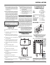
LOG SET
INSTALLATION
Read the instructions below carefully and
refer to the diagrams. If logs are broken
do not use the unit until they are replaced.
Broken logs can interfere with the pilot
operation.
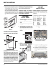
The gas log kit contains the following:
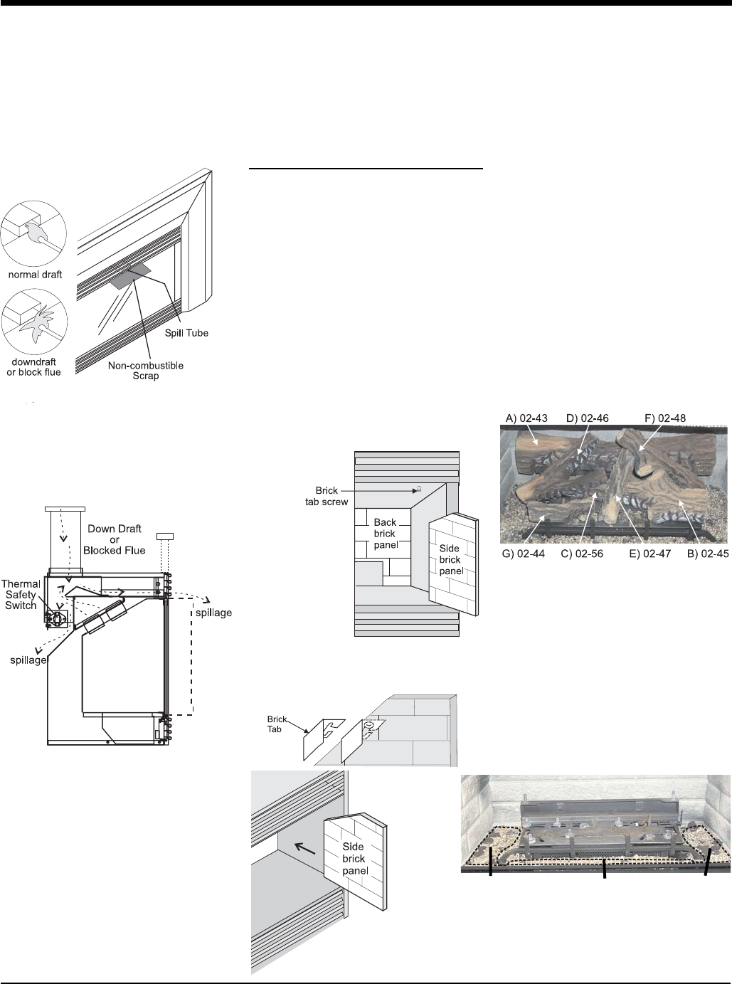
a) 02-43 Rear Log 902-227
b) 02-45 Front Right Log 902-229
c) 02-56 Middle Left Log 902-230
d) 02-46 Left Top Log 902-231
e) 02-47 Center Log 902-232
f) 02-48 Middle Right Log 902-226
g) 02-44 Front Left Log 902-228
h) Embers 902-154
i) Rockwool 902-153
j) Vermiculite 902-179/P
Note: Install Optional Brick Panels prior to
installing logs.
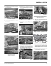
Vermiculite and
embers.
Vermiculite and
embers.
Vermiculite and
embers.
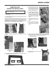
The "02" refer numbers (i.e. 02-43) are
molded into the rear of each log.
Diagram 1
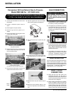
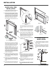
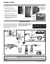
3) After fi ve minutes, test that there is a “pull” on
the fl ue by placing a smoke match, cigarette
or similar device which gives off smoke,
in front of the spill tube. To ensure a valid
test, place a scrap piece of sheet metal (or
other noncombustible material) between
the spill tube and the upper louver, this will
prevent the natural convection of the unit
from interfering with the test. See diagram
1.
Diagram 1
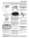
Diagram 2
Diagram 3
The smoke should be drawn into the spill tube.
If the smoke is still not drawn into the spill tube,
turn the unit off and check for the cause of the
lack of draft. If necessary, seek expert advice.
For wind turbulent sites, a wind cap may remedy
the problem.
Note: The thermally activated safety switch
will sense the change in temperature and shut
down the gas valve in the event of a severe
downdraft or a blocked or disconnected
vent. The switch acts as a safety shut-off to
prevent a build-up of carbon monoxide. If the
fl ue is blocked or has no "draw", the switch
will automatically shut off the supply of gas
within 5 - 10 minutes. Tampering with the
switch can result in carbon monoxide (CO)
poisoning and possible death.
If the heater turns off because of lack of draft
during the spillage test, check for the cause
and if necessary, seek expert advice.
The thermally actuated safety switch will
automatically reset after it has cooled off.
The switch will continue to cycle until the
draft problem is corrected. DO NOT BYPASS
OR DISCONNECT THIS SWITCH.
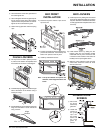
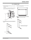
OPTIONAL
BRICK PANEL
1) Unwrap the brick pattern panels from the
protective wrapping.
2) Remove the glass front if it is already in-
stalled.
3) Put the rear brick panel fl at against the back
of the unit.
4) Before installing the side brick panels, loosen
the screws for the brick tabs enough so that
you can slide the brick tabs on to the screws
easily but that the tabs are secure. For the
location of the side brick tab screws see
diagram 1.
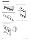
5) Remove the brick tabs and slide the side
brick panels into position. See diagram 3.
Install the brick tabs. See diagram 2.
INSTALLATION
1) Carefully remove the logs from the box and
unwrap them. The logs are fragile, handle
with care - do not force into position.
2) Sprinkle the vermiculite around the fi rebox
base. Take some of the embers (approx.
1/3 of the bag) and sprinkle over the ver-
miculite.