


7
FPI U31-2 Gas Fireplace Insert
INSTALLATION
NOTE: Mantel clearances for Installation into
a Zero Clearance Kit are different. Please
refer to the Zero Clearance Kit Manual for
details.
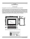
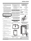
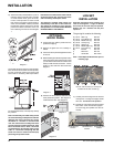
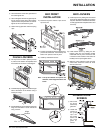
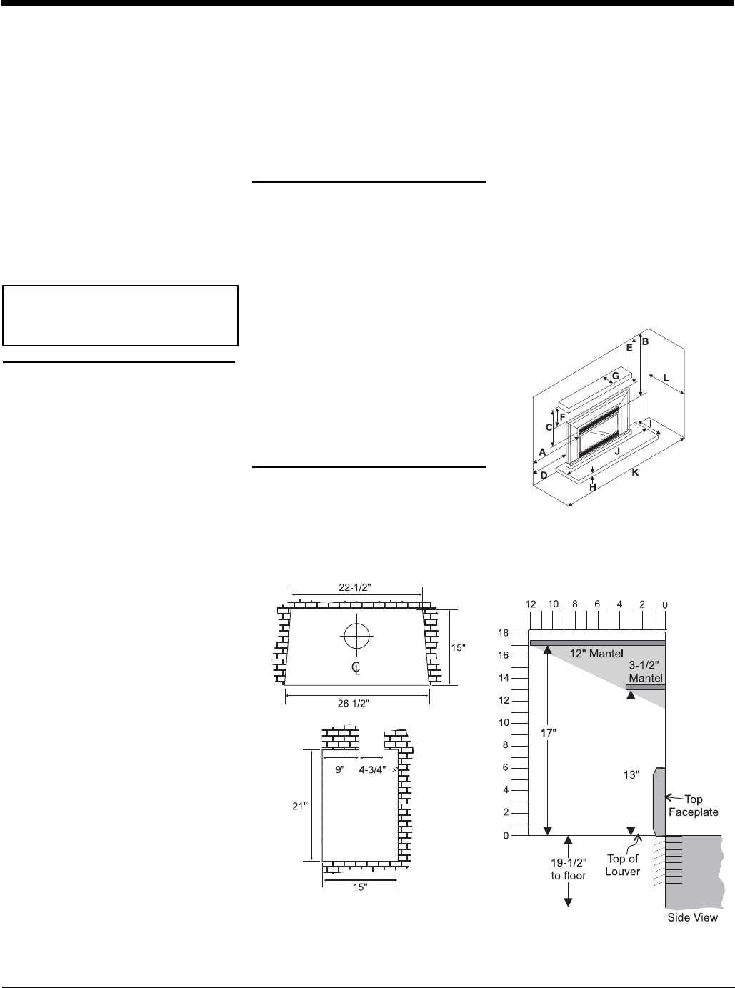
MINIMUM FIREPLACE
DIMENSIONS
The minimum fi replace dimensions for the FPI
gas fi replace insert are shown in the following
diagrams:
Combustible Mantel Clearances
with Bay & Flush Louvers in
Masonry Installation
Note: A non-combustible mantel may be
installed
at a lower
height if the
framing is
made of
metal studs
covered
with a non-
combusti-
ble board.
11) Failure to position the parts in accordance
with the diagrams in this manual or failure
to use only parts specifi cally approved with
this appliance may result in property damage
or personal injury.
12) Due to high temperatures, the appliance
should be located out of high traffi c areas
and away from furniture and draperies.
Children and adults should be alerted to
the hazards of high surface temperatures,
especially the fi replace glass and gold
trims, and should stay away to avoid burns
or clothing ignition. Young children should
be carefully supervised when they are in
the same room as the appliance. Clothing
or other fl ammable material should not be
placed on or near the appliance.
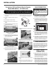
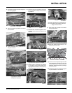
INSTALLATION
CHECKLIST
The FPI Gas Insert is installed as listed be-
low.
1) Unit Location - check Clearances to Com-
bustibles on page 6.
2) Make the gas connections (see page 7).
Convert to Propane Gas if necessary, page
7.
3) Install the fl ue or liner to the sliding draft
hood. See page 8.
4) Install Venting, page 8. Slide the unit into the
fi replace. Attach draft hood to the insert.
5) Test gas pressure, page 8. Check aeration,
page 8.
6) Test for fl ue spillage, page 8.
7) Install the optional brick panels. See page
9.
8) Install the log set. See page 9.
9) Assemble and install the faceplate and trim.
See page 11.
10) Install the glass front and optional Bay Front.
See pages 11 & 12.
11) Install both louvers. See page 12.
12) Install Optional Double Screen Door. See
page 12
13) Install Optional Remote Control and Optional
Wall Thermostat, page 20.
14) Final check: Before leaving this unit with the
customer, the installer must ensure that the
appliance is fi ring correctly. This includes:
a) Clocking the appliance to ensure the
correct fi ring rate.
b) Adjusting the primary air, if required,
to ensure that the fl ame does not
carbon. See page 10.
c) Ensuring that the appliance is venting
correctly. See page 9.
MATERIALS REQUIRED
No electrical power supply is required for the gas
control to operate. A 120 Volt AC power cord is
hooked up to the fan. Plug the 3 wire cord into
a suitable receptacle. Do not cut the ground
terminal off under any circumstances. When
connected with 120 volts, the appliance must be
electrically grounded in accordance with local
codes, or in the absence of local codes, with the
current Canadian Electrical Code CSA C22.1 (in
Canada) or with the current National Electrical
Code ANSI/NFPA 70-1987 (in U.S.A.).
NOTE: This unit is equipped with a heat sen-
sor thermodisc which will prevent the
blower from operating until the unit
reaches the correct temperature.
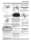
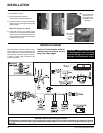
CLEARANCES TO
COMBUSTIBLES
From Unit
Sides A 10" / 255 mm
Ceiling B 47.5" / 1205 mm
Mantle C See mantle
clearances
From Standard Surround (26" x 40")
Sides D 4" / 100 mm
Ceiling E 41.5" / 1055 mm
Max. Mantel Depth G 12" / 305 mm
Hearth Height H 0" / 0 mm
Hearth Depth I 16" / 405 mm
Hearth Width J 40" / 1015 mm
Min. Alcove Width K 48" / 1220 mm
Max. Alcove Depth L 36" / 915 mm
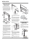
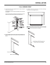
Note: If you are installing the Molded Faceplate
or Excalibur Surround, the minimum fi replace
dimensions are as follows:
Width (at front): 29" (737mm)
Depth: 16" (406mm)
Emissions from burning wood or gas could
contain chemicals known to the State of Cali-
fornia to cause cancer, birth defects or other
reproductive harm.