


17
FPI U31-2 Gas Fireplace Insert
HAMPTON CAST
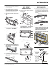
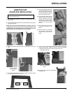
FACEPLATE INSTALLATION
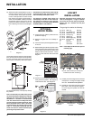
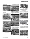
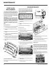
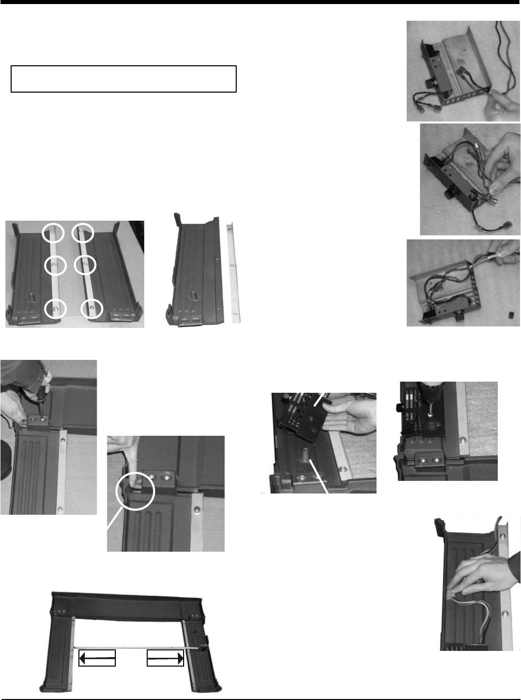
1) Lay the faceplate panels fl at, face down on something soft so they
don't scratch.
2) Attach the side fi ller brackets to the left and right sides using 3 screws
and washer per side.
3) Attach the right and left cast sides to the top using 2 screws per
side.
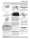
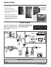
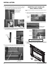
5) Connect the ON/OFF switch wires
by taking the black and red wires
with the blue female ends thru
the hole provided and connecting
them to the ON/OFF switch.
6) Connect the fan switch wires by
taking the black and red wires
with the male ends (in the grey
harness) thru the hole provided
and connect them with the wire
connectors from the fan speed
control.
7) Insert wires into the strain relief
and install into switch box as-
sembly.
8) Place the switch box assembly
over the boss on the rear left
side piece and secure with one
screw.
Ensure that the
top and sides are
aligned.
4) Use a measuring tape to ensure that the distance between the left
and right side pieces is 28" (711mm).
Switch Box Assembly
Boss on rear left side
piece.
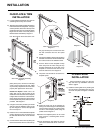
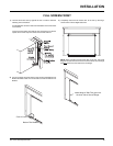
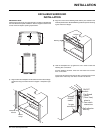
9) Tuck the wires into the faceplate to keep them away from the insert
using the clip provided. Attach the clip to the rear of the faceplate
to ensure that the wires do not touch the side of the unit.
NOTE: Do not install Cast Faceplate when unit is installed
into a Zero Clearance Unit.
28"
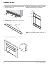
10) The power cord should be run behind the
faceplate panel.
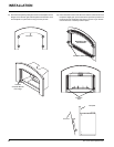
NOTE: There are fi ller brackets specifi cally for each side. The way
to differentiate this is that on the side of the brackets there are 2
mounting holes. The side where there is a 7/16" gap from the top
of the bracket to the mounting hole, must face the top.
INSTALLATION