


CB
WHITE
GROUND
BLACK
GREEN
A
B
C
PIDOMA
VOM
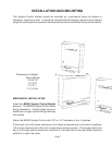
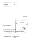
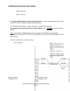
A sub-panel containing the disconnect switches and surge suppressors is required at or
near the equipment location(s).
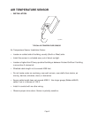
For accessibility remove the lower interior panel, by removing the four (4) access screws.
INSTALL CONDUIT AS APPROPRIATE.
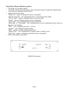
NOTE: Shielded cable, Belden #8132 or #9842 or equivalent, must be used to connect the
sensors to the System Control Module.
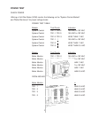
DIMENSIONS AND WEIGHT
System Control Module 19 1/2 lbs Boiler Monitor Module 21 1/4 lbs
15 3/16 L 17 1/2 L
12 1/2 W 18 3/4 W
4 3/4 D 5 1/2 D
ELECTRICAL CHARACTERISTICS
Control Module - 120 VAC, 0.5A; 60 Hz
Boiler Monitor Module - 120 VAC, 2.0A; 60 Hz
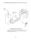
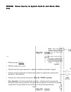
ELECTRICAL INSTALLATION
115 VAC FEEDER CIRCUITS
Install surge protection device(s) sized appropriately for your installation.
Install separate disconnect means for each load. Pull in appropriately sized wire for
equipment as defined by NEC and/or local code. All primary wiring will be 125% of minimum
rating.
It is strongly recommended that the System Control Module and the Boiler Control Module
be supplied from the same source power.
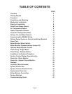
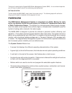
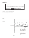
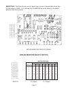
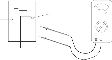
CHECK YOUR POWER SOURCE
Using a volt-ohm meter, check the following
voltages at the circuit breaker
Neutral (Return)
Hot
AC = 108 Volts AC Minimum, 132 Volts MAX
Hot to Ground
AB = 108 Volts AC Minimum, 132 Volts MAX
Hot to Neutral
BC = Must be less than 1.0 Volts AC
Neutral to Ground
Page 8