


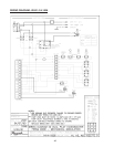
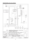
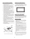
REFRACTORY PANELS TOP VIEW
HEAT EXCHANGER RE-ASSEMBLY
1. Heat exchanger water header O-rings should be
replaced with new ones.
2. Install in/out and return water headers and
install header retainer nuts and torque nuts evenly.
3. Install the four (4) corner clips between tube
sheets and refractory. Replace "V" baffles.
4. Install thermostat sensing bulbs in header wells
and replace bulb retaining clips.
5. Install inlet and return pipes in water headers
using pipe thread sealant.
6. Install water pressure relief valve, flow switch, and
low water cut-off devices (if so equipped).
7. Open water supply and return shut-off valves. Fill
heater and water piping system with water. Check
heater and piping system for leaks at full line pres-
sure. Run system circulating pump for a minimum
of 1/2 hour with heater shut-off.
8. Shut down entire system and vent all radiation
units and high points in system piping. Check all
strainers for debris. Expansion tank water level
should be at the 1/4 mark and the balance of
the tank filled with air.
9. Install flue collector, jacket top and inspection
panels. Install top holding screws. Install draft
diverter and vent piping if so equipped.
10. If gas piping was disconnected, reconnect gas
piping system and check for leakage using a
soap solution.
11. Check for correct water pressure and water level in
the system. Make sure that system pump operates
immediately on the call for heat. The system is
ready for operation.
12. Within two (2) days of start-up, recheck all air vents
and expansion tank levels.
COMBUSTION CHAMBER REMOVAL
To remove combustion chamber you must first
have removed the heat exchanger. Unbolt metal
combustion chamber retainer from top and remove
combustion chamber panels individually.
CONTROL WELL REPLACEMENT
Remove top, sensing bulb and clip. Collapse well
tube at the open and with a chisel, push through into
header and remove the well through header. Insert a
new well and roll into place. If a roller is not available,
solder the well in place with silver solder.
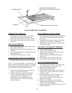
TUBE REPLACEMENT
1. Remove heat exchanger from heater following
instructions outlined under HEAT EXCHANGER
REMOVAL above.
2. Remove in/out and return headers. Remove
"V" baffle from damaged tube.
3. Remove damaged tube by cutting with a hack saw
or shearing with a chisel adjacent to each tube
sheet.
4. Collapse stub ends in tube sheets using a chisel or
screwdriver. DO NOT cut into tube sheet or mar
surface in tube hole in any way.
5. Insert replacement tube by inserting the end with
the most fins removed in the opening of one tube
sheet. Slide tube until the opposite end clears the
other tube sheet and fit the tube into the hole.
6. Insert the tube roller into tube opening up to stop,
making certain that 1/8" of tube projects beyond
the tube sheet.
7. Attach drill to tube roller, holding it straight and
level.
Note: Use a 3/8" heavy duty, reversible, electric drill or
larger. Proceed to expand tube until tool starts to grab.
Approximately 1/2 to 1" of the tool shank will be visible.
8. Reverse drill motor and withdraw tube roller, If
necessary wrench out by hand.
50
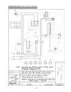
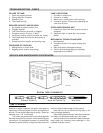
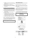
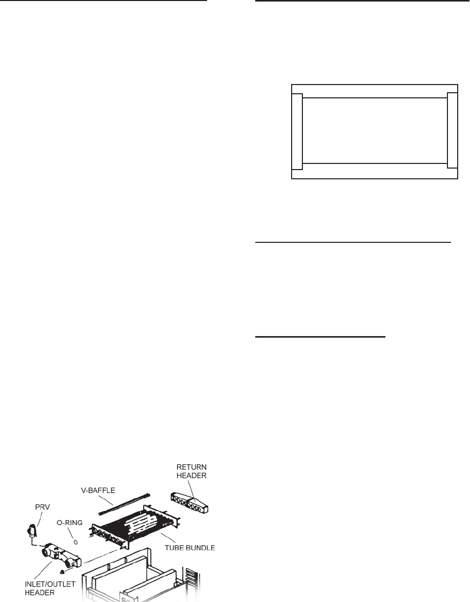
TYPICAL HEAT EXCHANGER CONFIGURATION
Fig# 9337