


36
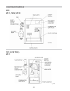
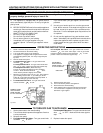
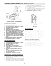
BURNER TRAY REMOVAL
1. Shut-off main electrical power switch to heater.
2. Shut-off gas upstream of heater.
3. Remove front door.
4. Disconnect gas line from gas valve.
5. Remove (2) screws that mount burner tray to unit,
and (4) screws that secure gas valve to jacket.
6. Disconnect wires that terminate at gas valve.
7. Unscrew (4) screws that secure the control box.
8. Disconnect pilot wire from the ignition module.
9. Disconnect wire harness from the combustion
blower.
10. Carefully slide out the burner tray assembly.
11. Reverse above procedure to reinstall.
GAS VALVE REMOVAL
1. Shut-off main electrical power switch to heater.
2. Shut-off gas supply to the heater.
3. Remove front door.
4. Disconnect gas line from gas valve.
5. Disconnect wires, pilot tubing and bleed line,
if required.
6. Remove (2) screws that secure gas valve to
jacket.
7. Turn vertical gas pipe from manifold slightly
and unscrew gas valve.
8. Reverse above procedure to re-install.
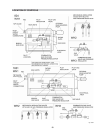
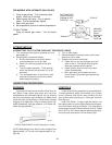
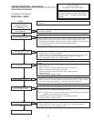
MAIN BURNER AND ORIFICE REMOVAL
1. Remove burner tray. (See Burner Tray Removal
procedure above.)
2. Remove (8) screws from the hold-down brackets.
3. Remove (8) screws from the left and right sides of
the manifold assembly. Detach the manifold as-
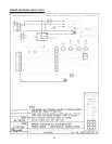
ADDENDA: LOW NOx HEATERS Models 181 to 401 (CONTINUED)
sembly from the burner tray assembly.
4. Use a long ½” socket wrench to remove orifices
from the gas manifold.
5. Remove burners by raising the bracket on the back
end of the burners up and out of their slots.
6. Reverse above procedure to re-install.
Fig # 9362
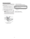
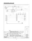
PILOT REMOVAL
1. Disconnect pilot tubing from gas valve.
2. Remove (4) screws from control box. Open the
control box.
3. Remove the pilot wire from the ignition wire.
4. Remove (2) screws that mount the pilot bracket
to the air manifold assembly.
5. Pull the pilot bracket downwards and outwards.
6. Reverse above procedure to re-install.
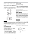
COMBUSTION FAN REMOVAL
1. Remove burner tray. (See Burner Tray
Removal procedure above.)
2. Remove (4) screws the mount the combustion
blower to the manifold assembly.
3. Reverse above procedure to re-install.
Fig # 9363
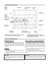
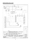
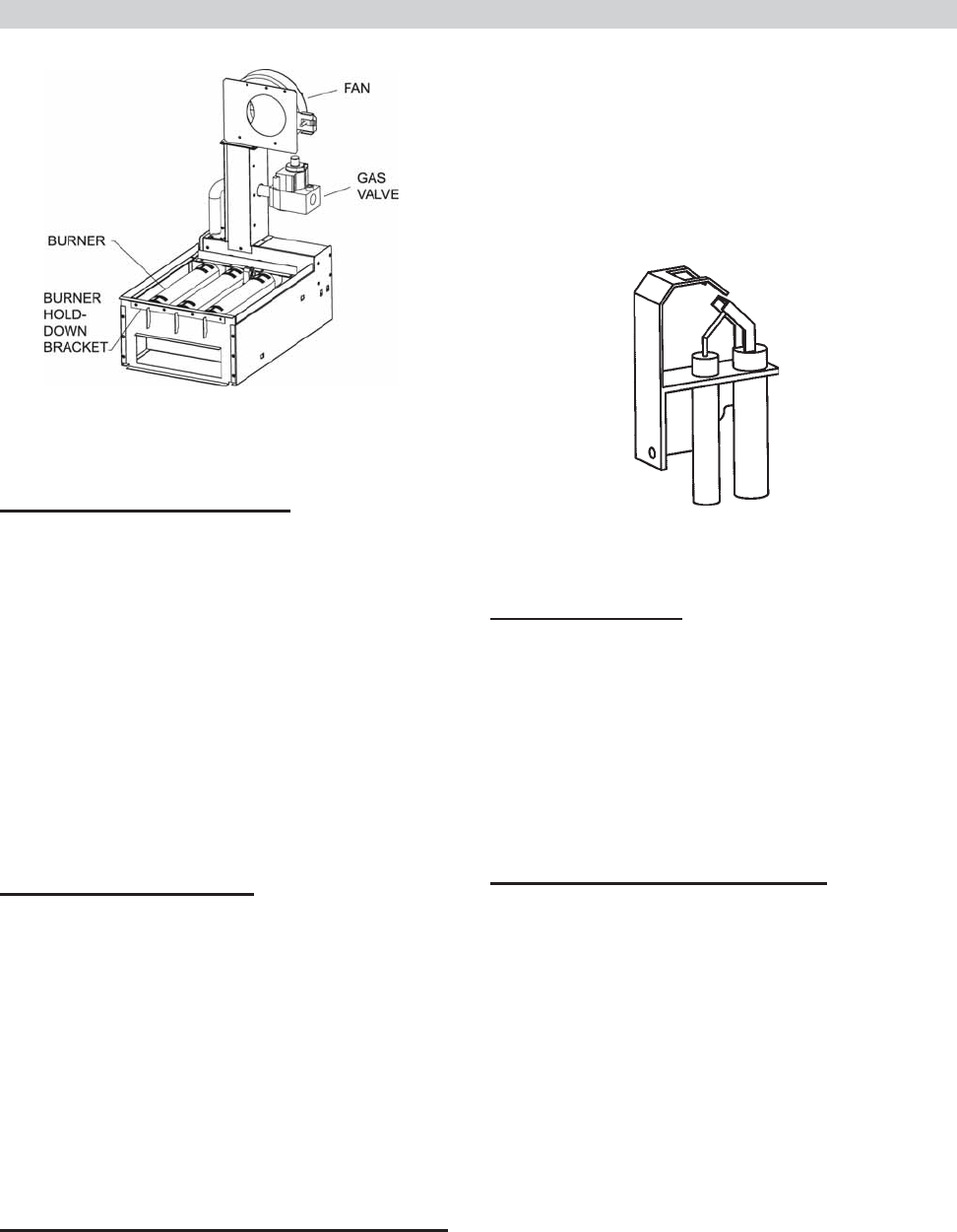
IID PILOT
LOW NOx BURNER TRAY ASSEMBLY